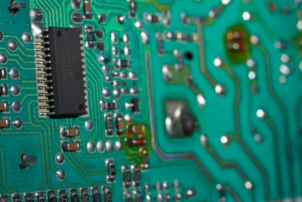
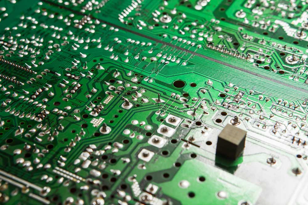
Circuit board assembly includes preparing and populating circuit boards with electronic components to make them functional. Typically, a circuit board will have drilled holes in which component leads are inserted. The details will be placed on the circuit board using any of the technologies, including surface mount. After the placement, the pins are then lined up using conductive pads to hold the components in place. If you choose to use PCBs with members on both sides, those on the bottom must be glued in place. They are then soldered, cooled, and solidified. If properly soldered, they will be electrically connected and held in place permanently.
1.Introduction of Circuit Board Assembly
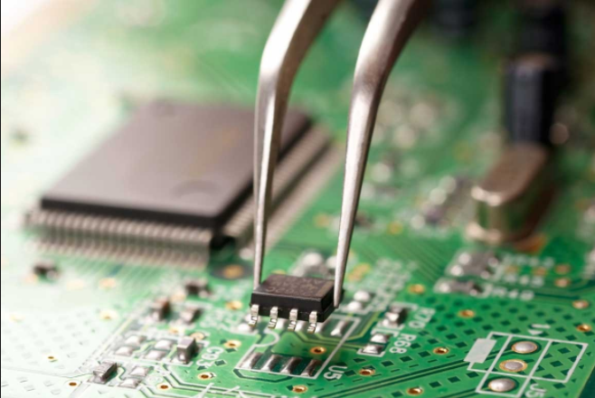
In-circuit board assembly, several techniques could be used to attach the components onto the PCB. A pick/place machine may be used in cases where a high volume of production is needed. Similarly, SMT placement machines and reflow ovens may be used to solder the components on the board. In cases where very tiny parts are to be soldiered, skilled technicians may do the job using tweezers and soldering iron. However, in the case of a small volume prototype, hand soldering may be inappropriate. Some SMT parts such as BGA packages cannot be hand soldered, so an alternative method must be used.
Often, both surface-mount and through-hole techniques may be used in single circuit boards assembly. This is especially the case where some components are already available on the surface, so combining the two methods in the community may be necessary. Also, either way, it could be used in cases where a few details are available in surface mount, packages, or through-hole packages. Both techniques could be utilized in other cases because through-hole mounting provides the needed strength for your components to improve their physic and enhance physical stress.
Now after populating the board, it should be possible to test it. Note that the test should be carried out when the power is off. Both automated and visual inspection may be used. Notice that both soldering and assessment are used to ensure that quality control is maintained. The voltage test may be used. When pads have been used, ensure that they are isolated using resistors before subjecting them to voltage tests. In-circuit tests may be used to help program the non-volatile components on your board.
2.Circuit Board Assembly—Protection and Packaging
This is the final stage in the Bill Of Materials (BOM) of a PCB to get fitted aboard. PCB assembly and entails coating your PCBs to protect them from an extreme environment. This may be done by spraying or applying dipping after soldering all the components. The coat is essential since it helps prevent corrosion and leakages that may be brought about by condensation or shorting. Another conformal coating such as Wax, or dilute solutions of polyurethane and silicone rubber may be used. Alternatively, you may sputter plastic onto the PCB. The trouble with these conformal coating is that it may be difficult to service the board later.