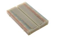
Breadboard
The breadboard is a plastic made structure with holes that are interconnected in horizontal and vertical directions by copper wires, hidden inside the plastic construct.
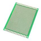
Pad-per-hole Perfboard
The breadboard is a plastic grid with holes stuffed by conductive pads to make the soldering process easier.
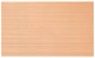
Stripboard
The breadboard is a type of perfboard where its holes are interconnected into stripes instead of single pad holes, so less soldering is required. It is easy to cut off the stripes to avoid short-outs.
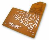
Homemade Etched PCB
The breadboard is a board that resembles the factory-made PCB. It uses a random printed circuit on laminated paper, copper plate, and copper etching using acids, hydrogen peroxide, and lukewarm water.


NXP France
In the electronics industry, the circuit board is the backbone of almost all the circuits. It is not wise to build the circuit schematics and then send them straight away to PCB manufacturers for fabrication. What if the resulted PCB does not work?
So, it is always recommended to test your circuit diagram first. There are many electronics prototype boards available in the market. They are reliable, cheap, high-performing, convenient to work with, and can work with all component sizes.
In this guide, you will learn all about the different electronics prototype boards available in the market. Stay tuned.
1. Electronics Prototype Boards
1.1 What is an electronics prototype board?
In simplest terms, you use electronics prototype boards for testing your project when it is in its early stages. This board can have a mesh of tiny holes to which you can affix electronics components. These components can be attached with or without solder depending upon the type of board.
Hence, we can say that electronics prototype boards are for temporary testing and construction of electronic circuits. You will find it more appropriate to develop your design on a board that is for prototyping.
1.2 What options are available in the market?
Currently, in the market, you will come across a breadboard, stripboard, and a perfboard. The following subsections are for these types of electronics prototype boards.
1.2.1 What is a breadboard?
A breadboard serves as a structural base for testing your electronics. It is mostly developed from white plastic and doesn’t need solder for attaching the components. Thus, this board type can be re-utilized. Figure 1 shows a typical breadboard.
You can use it for a variety of projects varying from simple to high level digital or analog circuits. That is not it, central processing units (CPUs) can also be prototyped using these boards.
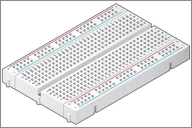
Figure 1 A typical breadboard that is quite common among the students
1.2.2 What is a Stripboard?
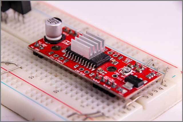
Stripboard is a type of electronics prototype board that has 0.1 inches rectangular network of holes. It also has extensive analogous copper strips arranged in one direction on one of its sides. Moreover, they are also known by the name of Veroboards. Figure 2 illustrates the components soldered on a Veroboard.
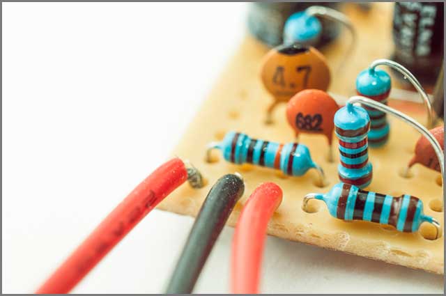
Figure 2 Electronics components soldered on Veroboard
1.2.3 What is a Perfboard?
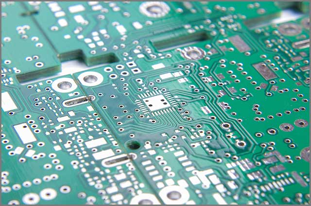
Perfboard is a stiff, thin sheet with holes bored at regular places on a grid. The grid is mostly a squared shape with a spacing of 0.1 inches. Square copper pads cover these holes, but plain boards also exist. You will need to use solder for attaching your components. Figure 3 demonstrates a Perfboard.
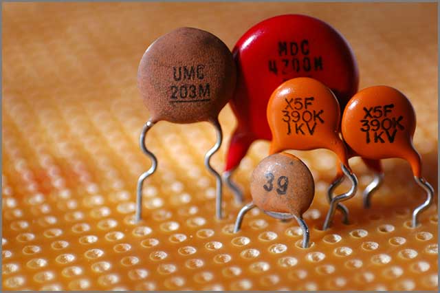
Figure 3 Capacitors placed on a Perfboard
In this section, we discussed the basic definition and different types of electronics prototype boards. In the next one, we will tell you about how to use them.
2. How to Use Them?
2.1 Breadboard
For prototyping purposes, you can easily place your electronic components into the holes of the breadboard. There is no need of using any specific tools for using the solderless breadboard. But, if your electronic components are too small, you may use tweezers or pliers for picking and placing them.
Some breadboards have labels over them to make it easy to use for the first time. In Figure 4, you can observe that there are two strips of holes lying in between “+” and “-” labels. Further, the central columns of holes are labeled as “a, b, c, d, e” and “f, g, h, i, j.”
Keep in mind that every row of five holes (a-e or f-j) are electronically connected. There are no electrical connections present between the holes of anyone half-row with any other half-row holes. For instance, f1 is connected to g1, h1, i1, j1, but not to a1, b1, f2, g4, h2, etc.
For the two holes strips running in between “+” and “-” the electrical connection is present throughout each whole column strip. You can use them for providing power and ground connections to your electronics circuit.
2.2 Stripboard/ Veroboard
You would need to place the components on the copper-free side of the board. You would observe that their legs would be coming out of holes on the other side of the board. This side has copper tracks, so you will solder these legs on this site to make the required connections.
2.3 Perfboard
You should first plan your project’s connections and locations before developing the circuit on a perf board. PCB layout software or similar ones are for such planning. Moreover, it would help if you also kept in mind your surfboard’s spacing while designing the layout.
After that, you would need to solder the components at their places and make any required electrical connections. To avoid excessive use of wires, you can use leads of components like resistors to make these connections. However, you can use electrical cables on the copper side of the perfboard whenever needed.
In this section, we told you about using the electronic prototype boards. In the next section, we will notify you about their advantages and disadvantages.
3. Advantages and Disadvantages of Electronics Prototyping Boards
3.1 Breadboard
3.1.1 Advantages
You can quickly make your circuit or do any changes.
It works perfectly with the dual in-line package (DIP) ICs.
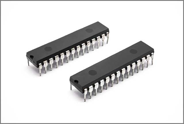
Figure 5 DIP ICs
3.1.2 Disadvantages
It offers only lab testing, so reliability is limited.
There is a high capacitance present between two rows.
They are limited to components with small legs.
3.2 Stripboard/ Veroboard
3.2.1 Advantages
You can easily make amendments to your circuit.
Can be used permanently.
Readily available in the market
Cheaper than printed circuit boards (PCBs).
3.2.2 Disadvantages
Here again, you will get limited reliability.
The circuit layout is large.
You need solder, which is not a problem if you are an expert.
3.3 Perfboard
3.3.1 Advantages
If you solder the circuit well, you will get reliability.
Can be used permanently.
Quite cheap.
Work with almost all sizes of components.
You will feel comfortable while using the discrete components
3.3.2 Disadvantages
It consumes time.
You need to have expertise.
You may find it hard to use it with ICs.
In this section, we discussed the advantages and disadvantages of electronics prototype boards. In the next chapter, we will tell you about the common mistakes that you may do while using them.
4. Common Mistakes While Using Prototype Boards
Well, as a beginner, you would make inevitable mistakes while making connections on electronics prototype boards. So, this section will make sure that you do not do so. Keep on reading.
You may make the following mistakes while using a Breadboard, Veroboard, and Perfboard:
You can get the row numbers wrong while using a breadboard. So, if your circuit is not working, you should check if you have wrongly placed any component.
While using breadboards, you can also get confused between which column strip was set to provide power and which was set to ground. So, don’t mix them up.
It is possible that you have not pushed the electronic components through the holes in the breadboard. So, try not to make any loose connections.
In all types of prototype boards, some components may be placed in the wrong order. Therefore, you should always check the polarities of your electronic components.
In Veroboards or perfboards, you may have wrongly soldered your components. Or, you may have put too much solder that two connections are getting short-circuited, so if your circuit is not working instantly, double-check for soldering errors.
In surfboards, you can mix up the copper-free side with the copper side. So, look closely to identify each side of the board.
In Veroboards, you may start connecting your circuit without proper planning, which may lead to a faulty board.

5. Get PCB Prototypes from WellPCB
If you are worried that the above-discussed prototype boards are not what you are looking for. You want a board that doesn’t have any restrictions and can be used in any project or with any components. Then you are in luck. We have the right prototype board for you.
There is a universal electronics prototype board available in the market – the printed circuit board (PCB). All you need to do is to make a PCB layout of your circuit diagram and send it to a company for making its prototype.
Luckily, you can get PCB prototypes from WellPCB and at very cheap rates. That will save you time and money. WellPCB also offers various promotions and services for its valuable customers. You can visit their website here to know more.
Conclusion
This article discussed the electronics prototype boards through which you can quickly build and check your circuit. All you need is an electronics prototype board that is reliable, cheap, and works for all component sizes. We discussed the different types of these boards with their advantages and disadvantages. That was all to make it easy for you to select a board that fulfills your requirements.
Now, you are all set to prototype your electronics circuit in real-time. Still, if you have any questions, please feel free to contact us at any time. We are always ready to help you with any queries.