
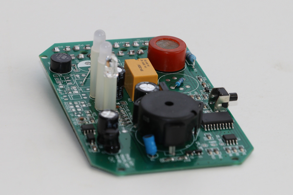
This is a project about HC SR501 which wrote by an engineer who had ordered our boards.
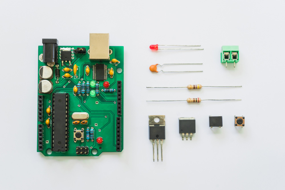
Whether you are in a bathroom or your study room, it makes life easier for you to automate the lighting system such that you do not have to switch every switch on. It is much more natural and enjoyable to let the lights behave the way you want without getting involved. To do a good job, you need to purchase some PCBs or instruct some wellpcb.com) to do the job for you. In this tutorial, you shall use a couple of Printed Circuit Boards, which can be termed standard since almost all electronics enthusiasts and professionals use them.
In addition to this, you will also need a 5V DC voltage source to power the Arduino and a light source, which is the normal bulb for your house lights.
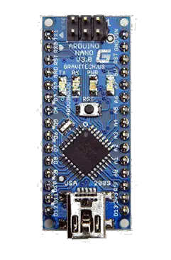
First, we need to program our Arduino to give the actuating signal whenever a human being makes some movement. The working sequence is simple. The PIR Sensor stays on standby, waiting to detect any infrared signals registered from movement from a human being. When movement is registered and acknowledged by the Arduino, the Arduino issues a high signal to the relay module, telling it to close contact for the light switch so that lights can go on since somebody is moving and needs some lighting. Where there is no movement recorded, lights go o. To keep this all working as it should, one must include some timing between the Arduino program to ensure that it waits for the right data and does not perform actions too quickly or based on erroneous data.
To get started, we shall start with a simple program using Arduino IDE. This program will be in control of our system. The program should be similar to the following:
//Control | lights using hc sr501 PIR Sensor PCB; | ||
int | pir = | 2; //PIR at pin | 2 |
int | relay | = 3; //Relay at | pin 3 |
Steps:
1.HC SR501—void setup()
{Serial.begin(9600); pinMode(hc sr501 pir, INPUT); pinMode(relay, OUTPUT); digitalWrite(relay, LOW);delay(5*1000); //Wait for the PIR to settle}
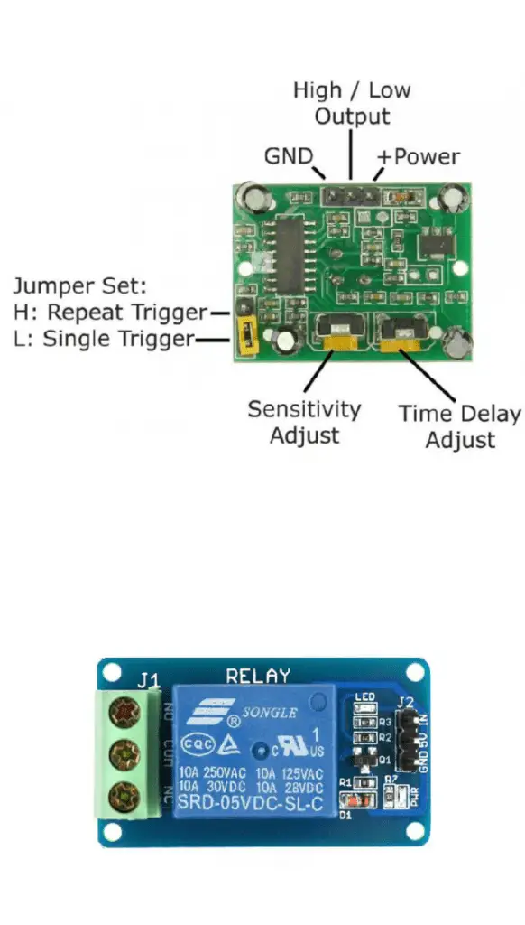
2.Connect the power pin of the hc sr501 PIR Sensor board to the Arduino 5V and GND pin to the Arduino ground pin.
The output pin of the sensor should be connected to the Arduino pin 2. You could change this to suit your program. Note that in this, when connecting, you may need male to female jumper wires. In most cases, you leave all the other sensor settings the same as the factory settings. If, for some reason, the sensor behaves in an undesirable or unexpected way, you can come back and increase the sensitivity or lower the delay time.
3.HC SR501—The Arduino pin 3 should be connected to the IN pin of the 5V relay channel.
The 5V and the GND pins on the 1 channel relay should be connected to the 5V source and common ground. Normally, the other side of the relay channel Normally has Open (NO) contacts and Normally Closed (NC) contacts. We will use the NO contacts so that the circuit shall be o even when the system is not powered. A house light bulb has a switch. This switch has two contact points. These two contact points come together to let the current ow and power the lights. Switch o the main switch and connect these two contacts to the NO contacts of the relay board. Note that this exercise could be hazardous and should only be performed by or with a responsible licensed electrician; unless you know what you are doing.
4.Having made all these connections right, power your circuit again.
Give the sensor some time for it to settle. Now wave your hand in front of the sensor for some time, then remove your hand and settle for some time. You should see lights go on when you wave your hand and goo when you remove your hand and settle. The project is complete! You can now go ahead and make a decent implementation of this prototype in your house.
Partner: Sam