It is said that the eyes are sensing things that our mind reads and the same is the case with the LDR known as a light-dependent resistor. The LDR is sensing the light and giving an output. The statement is right that you can either make any switch ON or OFF depending on the requirements; however, we are often showing carelessness which is resulting in an increased bill of Electricity and energy is also wasted. For this purpose, the light detector circuit is being designed using a Wheatstone bridge, which is very useful in energy saving.
The light detector circuit using Wheatstone bridge is working in a manner when light is sensed by the Light Dependent Resistor, the circuit switch off all the lights inside a building. A relay is being used for the smooth operation of the circuit. All the light sources inside a building are being controlled through LDR to minimise the electricity use and bill. The circuit is found to be very useful to save energy and minimise the electricity bill.
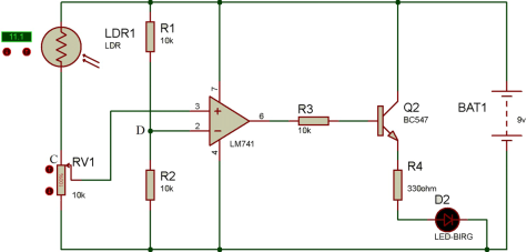
1. Basic Circuit Diagram
The following is the basic block diagram of the light detector circuit using Wheatstone bridge.
2. Safety precautions
The safety precautions were recommended by the well PCBs and were followed. However, the light-dependent resistors are very sensitive to all sources of light. Therefore you need to be very careful if you have the sensor circuit in your house or room. In addition, you have to take care of the artificial sources of lights, e.g. electric bulbs. This is because the sensor circuit will trigger all lights off when it senses lights each time it senses light.
3. Notes
1. The circuit is working on even very low light sources.
2. There is no need of having additional capacitors in the circuit.
3 There is a need of variable DC supply in the circuit.
4. Main Working of the Circuitry
The light-dependent resistor is a resistor which is varying its resistance with the strength of the light at different places. The resistor is made of cadmium sulphide. When the resistor is not sensing any light source, its resistance is huge and is in Mega ohms. Whereas when the light-dependent resistor senses a light source, the resistance automatically reduces. This means that when there is light, the light-dependent resistor has an output and when there is no light, the light-dependent resistors have no output. Therefore, it can be simplified that the light-dependent resistors can differentiate between light and darkness, or day and night.
The Wheatstone bridge is used for the detection of the voltage drop in between the different resistors. In the light-dependent resistors, the Wheatstone bridge consists of an LDR connected with a potentiometer in the first arm, which has a resistance of 10K ohms or more and a resistor in the second arm. When the light is incident on the light-dependent resistor, the resistance is getting lowered. In return, the voltage is changed at the potentiometer and detected, and hence the required decision is made.
The light-dependent resistor is working on the principle of the conductivity of photons. As the light is falling on the surface of the light-dependent resistor, the sensor’s resistance is decreasing, and in turn, it gives an output. This is due to the transfer of electrons from the valence band to that of the conduction band and due to the high energy of the photons present in the incident light.]
5. Components Required
The following are the basic components required to make the light detector circuit using the Wheatstone bridge.
1. LDR
2. Transistor (BC547)
3. LM741op-amp IC
4. Potentiometer (10k)
5. Resistance (10k, 330ohm)
6. Led (red)
5.7. Battery (9v)
6. How To Using Light Detector Circuit—Features
1. The resistance of the cell is only 400 ohms and can vary up to 9-kilo-ohms.
2. The resistance of the LDR is in mega ohms in darkness.
3. The rise time is about 48 to 120 milliseconds and fall time is about 2.8 to 1.2 milliseconds.
4. This has a wide spectral range.
5. The project is economical when cost is considered.
6. The project is working perfectly even in high ambient temperatures.
7. How To Using Light Detector Circuit—Applications
1. The project can be used in automated street lights.
2. It can be used in the position sensor.
3. It can be used in the intensity meters for lights.
4. It is used in the burglar detection circuits.
5. It can be used in the automated bedroom lighting.
6. It can be used in the LED-based obstacle detection systems.
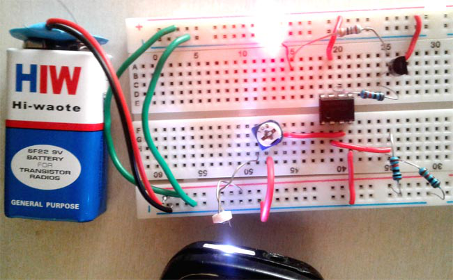
8. Implemented Photo of the Light Detector Circuit using Wheatstone bridge