Transistors can be complicated electronic components. So much so that people often mistake and conflate transistors with resistors. However, transistors are far more varied in type and use. This guide will explore one in particular – the SL100 transistor. We’ll cover how it differs from other transistors, its structure and when to best use it.
What is an SL100 Transistor?
The SL100 is an inexpensive multi-purpose bipolar junction NPN (negative-positive-negative) transistor. It’s a low-to-medium power transistor. Thus, it’s suitable for beginner circuit board projects.
SL100 Transistor Pin Configuration
As with most NPN transistors, the SL100 transistor consists of three terminals (AKA pins). They are as follows:
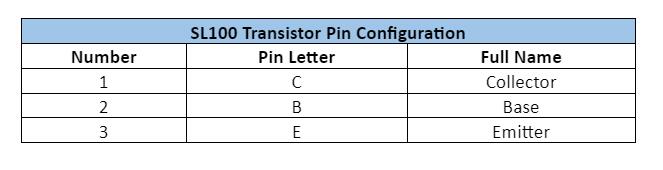
Emitter: A terminal with the highest doping levels on the transistor. It attracts charges from the collector through the base and releases them.
Base: The middle terminal. It works as a trigger for sizable collector-to-emitter currents. When the base receives sufficient voltage, a large current flows through from the emitter to the collector.
Furthermore, it typically operates at a current of 0.7V and above. We can easily manipulate the voltage at the base to change the current flow through the transistor. The base is often thinner than the emitter or collector. Thus, it offers the least resistance, making it easy for current to flow through from the emitter to the collector.
Collector Collects charge carriers from and pushes them through to the emitter in an NPN configuration. Inversely, the current will flow out of the collector in PNP configurations.
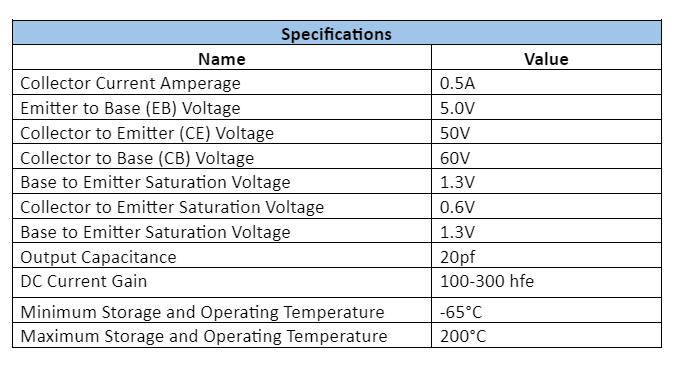
Features and Specifications
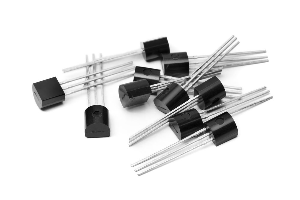
Collection of TO92 transistors on a white background
The SL100 has a few unique specifications and features you need to understand. Because of their TO-39 package, SL100 transistors are quite rugged and resilient. They can operate under extremely low and high temperatures.
Furthermore, they have easy drive requirements and are relatively easy to handle and use. Nevertheless, the SL100’s most significant specifications are:
SL100 Equivalent Transistor
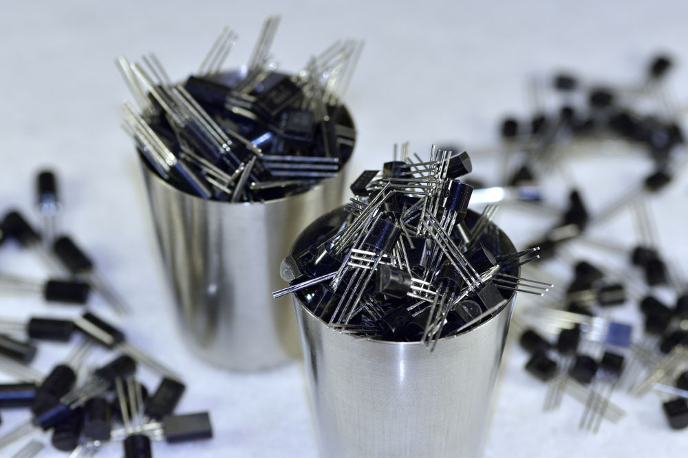
Collection of low-power transistors in metal cups
The SL100 may not be available in your region. However, there are other transistors with similar specs and capabilities. They are as follows:
- 2N6371H
- PN100
- PN200
- MZT3055
- P2N2369
- P2N2369A
- P2N2907A
- 2CF2325
- BD675BPL
- BF422BPL
- BC548B
- 2N3904
- 2N23867
- 2N3055HV
- A1941
- BD237S
- BU908F
- BC301
Where to Use SL100 Transistor
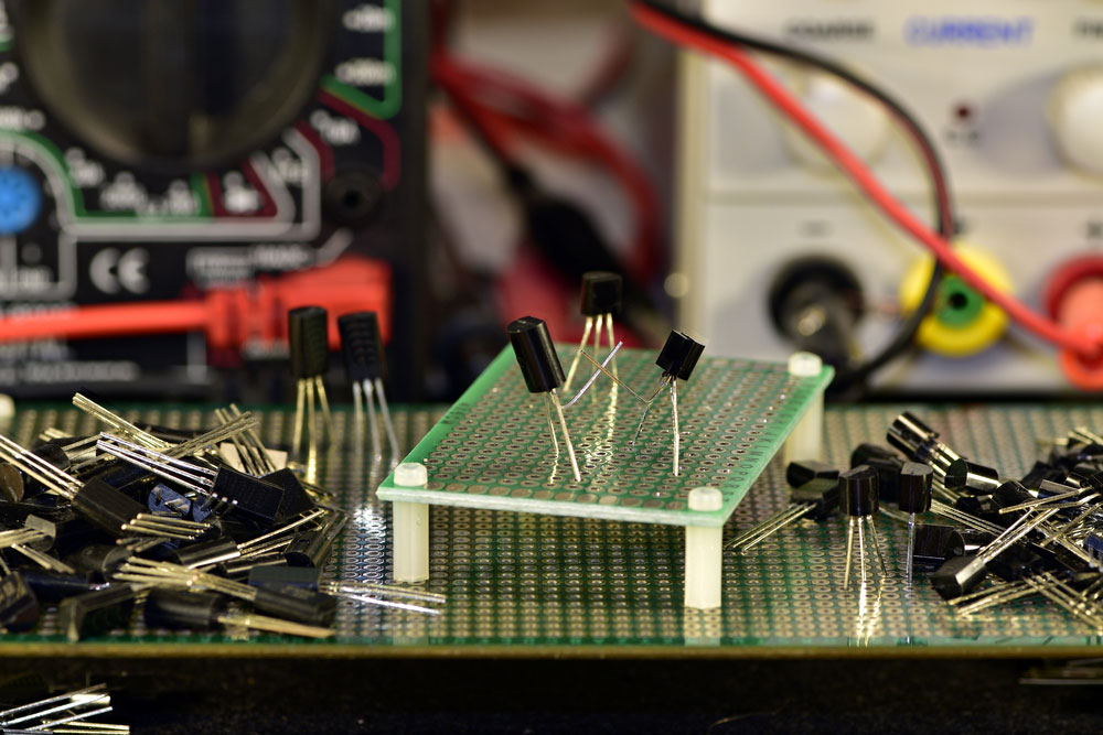
A collection of low power transistors on circuit board
Because the SL100 is a general-purpose transistor, it’s suitable for a wide variety of applications. For instance, you can use an SL100 to build simple projects such as a continuity tester that outputs auditory and visual signals. Furthermore, we can use it to develop low-power amplifier circuits. Alternatively, we’ve seen the SL100 in more advanced projects such as moisture level and detection devices. Other general electronic applications include:
- Solar chargers
- Signal processing circuits
- Switching circuits
- Beeper circuits
- Manufacture of logic gates
- Streetlight circuits
- Amplifying circuits (sound reproduction and signal amplification)
- Automatic emergency lights
- Radio transmission processing
- Gas sensor alarm circuits
- Automatic voltage stabilizers
How to Use SL100 Transistors
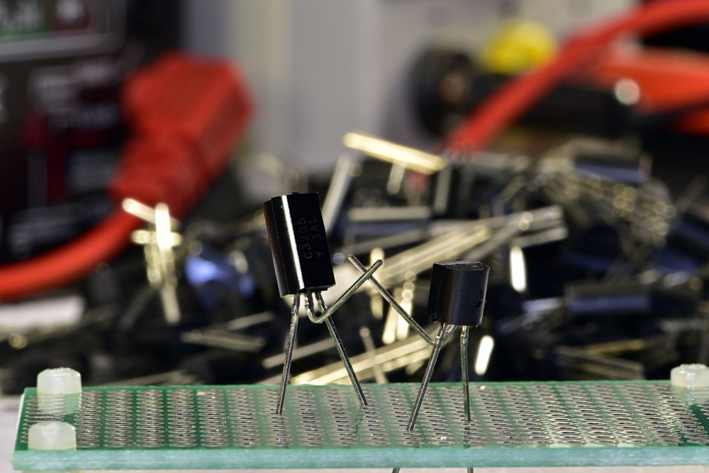
TO-92 Transistors mimicking a high-five on a circuit board
This section will show you a practical example that you can use to build your very own SL100-based project.
The following circuit will require:
- 9 Volt battery x 1
- 1K Ohm resistor x 1 (R1)
- 500 Ohm resistor x 1 (R2)
- Red LED (D1)
- Switch
- SL100 transistor (Q1)
Circuit Diagram:
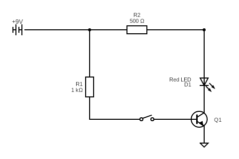
Title: Simple circuit diagram using an SL100 transistor
The above circuit uses a 9-Volt battery as its power source. However, you can replace it with any DC power supply or voltage. Again, it’s a simple circuit that turns on an LED when the current successfully passes through it.
You can interrupt and restore the current using the switch. Thus, when we close the switch, the current flows through the collector before pushing it through the base. Once the current reaches the base, it flows through to the emitter. The emitter releases the current into the red LED which turns on to signify that it has received it. Once more, you don’t have to use a red LED as a light source.
You can reconfigure and customize some of the components in this circuit. Essentially, the goal here is to test the function of the SL100 transistor. Nevertheless, once you’re finished with this project, you can move to more advanced LED voltage indicator projects.
SL100 vs. BC107 Transistors
When we listed our alternatives for SL100 transistors, you’ll notice that we did not feature the BC107 transistor. Why?
In most cases, the BC107 transistor is similar in structure and function to the SL100. For example, it uses a TO-18 metal can package. Besides, it looks almost identical to the SL100’s TO-39 package.
Furthermore, it is an NPN bipolar junction transistor. We typically implement it for switching and signal amplification purposes. Again, just like the SL100 transistor, the BC107 has three different terminals. These are its similarities to the SL100, but what are the differences?
Firstly, the name of the transistors is a dead give-away. Concerning the SL100, the name indicates that it’s the 100th version of a silicon NPN transistor. The BC in BC107 stands for the buried channel.
Furthermore, It’s a PNP type transistor. Whereas the SL100 is an NPN transistor.
With 50 volts, the SL100 has a higher collector to emitter voltage. Comparatively, the BC107’s CE voltage is 45V.
Moreover, the SL100 has high power dissipation. It has 800mw of heat dissipation compared to the BC107’s 600mw.
Additionally, the BC107 has again below 30dB, which is lower than the SL100’s 100dB. Another area where these two transistors differ is in power gain. The SL100 has a power gain between 125 and 500 hFE.
In comparison, the BC107 has a power gain between 100 and 300 hfe. Both have identical storage and operational temperatures (-65°C to 200°C).
SL100 vs. BC547 Transistors
The BC457 is another transistor we did not include in our list of alternatives. Much like the BC107, the BC547 is a buried channel transistor. It’s available as an SMD and TO-92 package. Both the BC1547 and SL100 are NPN transistors that consist of three junctions.
The BC547 key specs are as follows:
- Maximum Collector Current: 100mA
- Maximum CE Voltage: 45V
- The Maximum CB Voltage: 50V
- Maximum EB Voltage: 6V
- Maximum Collector Dissipation: 500mw
- The Maximum Transition Frequency: 300 MHz
- DC Current Gain: 110 – 800hFE
- Minimum Storage and Operating Temperatures: -65 to 150 °C
- Noise Gain: 2-10 dB
One of the biggest differences between the two transistors are their current gains. The BC547 has a maximum current gain of 800hfe compared to the SL100’s 500. However, the SL100 has higher collector to emitter, collector to base, and emitter to base values.
Nevertheless, the BC547 may be more flexible in usage because of its high transition frequency than the SL100. We can integrate the BC547 into radio-frequency circuits. Similar to the SL100, the BC547 is suitable for current and signal amplification usage.
Moreover, we can use it in quick switching applications. BC547 transistors also work well as Darlington pairs.
Conclusion
Once again, because of their wide availability and economic accessibility, SL100 transistors are great for easy beginner projects. However, because most transistors are typically inexpensive electronic components, you should not shop by cost but by specifications. There are many alternatives to the SL100 transistor. Thus, when deciding on which transistors to choose, you must understand which printed circuit board you’ll use it in and your project’s requirements.
