In recent times, technology has seen tremendous strides regarding the evolution of electronic circuit components. For instance, the transistor now has several JFETs and BJTs. In this case, however, we focus on a type of high-speed joint field-effect transistor, the TL072 pinout.
The TL072 pinout is the IC for you if you intend to take on projects that require bass or treble control. This includes audio circuits, UPS, AC inverters, and solar inverters. Further on, we discuss all this operational amplifier, its pin configuration, and usage methods.
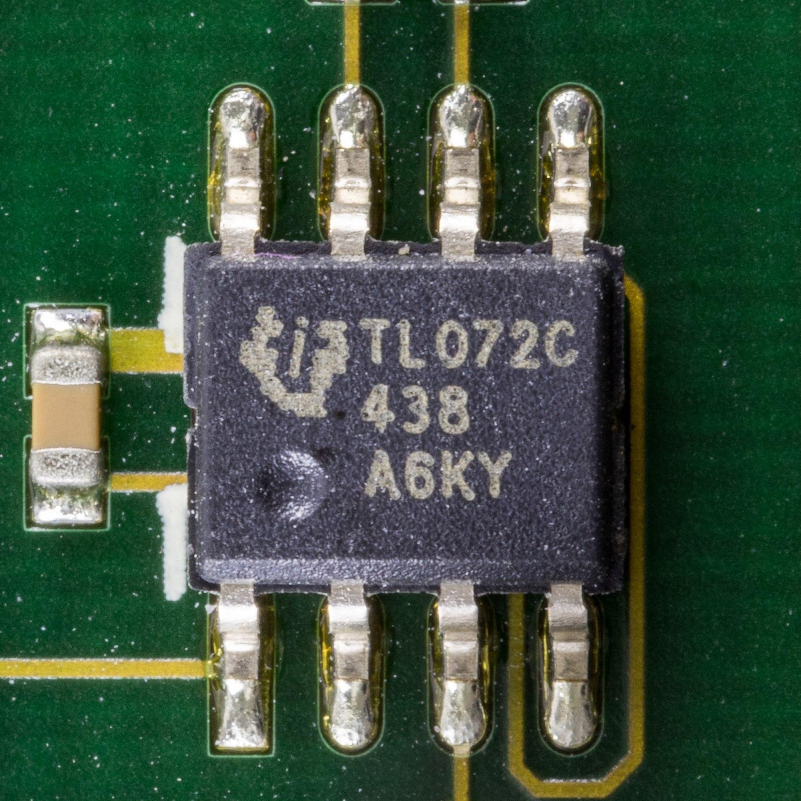
(A pictorial view of the TL072C low-noise JFET input operational amplifier in a SOIC package).
Source: Wikimedia
TL072 Introduction
To begin with, the TL072 pinout is a bipolar high-speed junction field-effect transistor (JFET). To most, it is an upgrade to the single version TL071 that uses one op-amp only. However, it also works as a dual input general-purpose operational amplifier depending on specific applications.
In addition, the dual op-amp IC has many exciting features. For instance, it has reduced power consumption, low thermal noise, temperature coefficient, and higher slew rates. All these, in conjunction, make the TL072 dual low-noise JFET IC unique.
Therefore, you find them crucial electrical circuits with modular designs. Some include UPS, AC inverters, solar inverters, oscilloscopes, and audio signal gain applications.
(TL072 is a JFET)
TL072 Pin Configuration
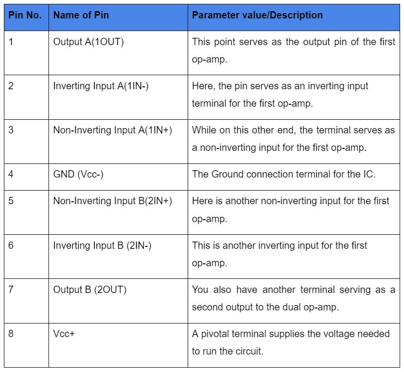
In total, the TL072 pinout configuration includes eight pins, each serving a unique function.
(An equivalent dual op-amp IC pin diagram)
Source: Wikimedia
Below, we list the names of the eight different pins with their parameter values.
TL072 Symbolic Representation
By convention, the TL072 pinout comprises a duo of internal amplifiers. Therefore, the op-amp IC symbol is a result of that internal configuration. Subsequently, we represent the TL072 pinout with a schematic diagram.
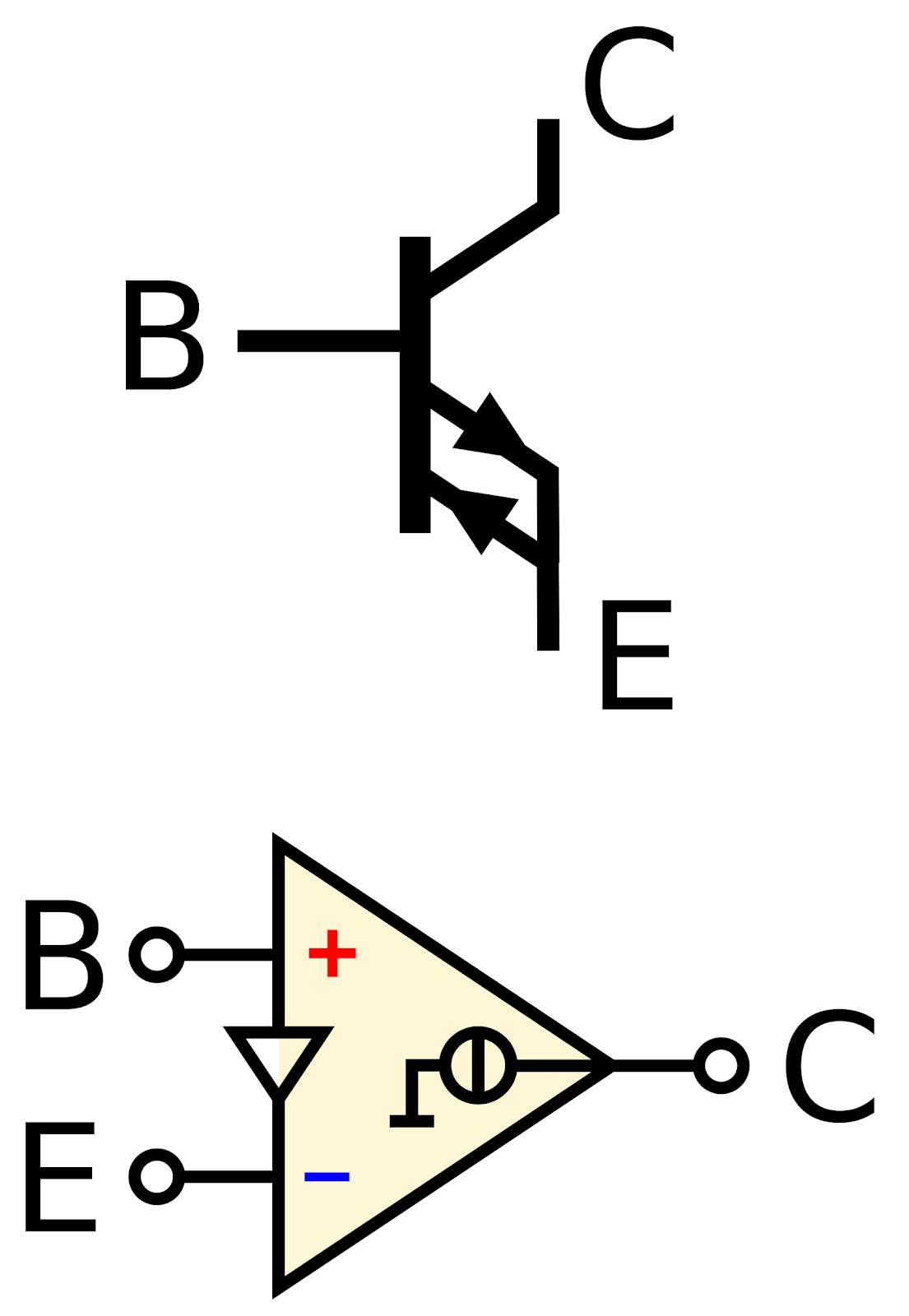
(Above, the symbolic diagram shows the presence of two amplifiers in the TL072 IC).
Source: Wikimedia
How to Connect the Amplifiers to the IC
To do this first, you connect the amplifier to PINs one and three of the IC. Meanwhile, the output goes to pin 1 OUT of the TL072 IC.
On the other hand, you run a connection for the second amplifier to pins 5 and 6. At the same time, you connect its output to pin 7.
TL072 IC Technical Specifications
Generally, the TL072 pinout is a preferred op-amp IC for its numerous incredible features. Below, we list some of the outstanding features and technical specifications of the TL072 IC:
- It is a low noise IC with high slew rates.
- Also, it has a low harmonic distortion circuitry.
- The audio op-amp possesses an extended standard mode voltage ranging between 6V and 36V.
- The TL072 has a low bias voltage.
- Low power/current consumption. In other words, it uses a quiescent current ranging from 1.4mA to 2.5mA.
- Furthermore, it uses less input offset current as well.
- Unlike others, the TL072 features short circuit protection at the output.
- Furthermore, it makes up for inadequate internal frequency.
- A latch-up-free operation mode.
- Finally, it is reliable and affordable.
Applications
Overall, the TL072 pinout has a wide range of applications. However, we list a few significant applications involving the dual input general-purpose operational amplifier IC:
- AC inverters.
- Audio circuits.
- Oscilloscopes.
- Solar and other solar components.
- DLP front projection systems.
- Uninterruptible Power Supply (UPS).
- VF drives.

(Solar systems use the Tl072)
How to use TL072 Pinout in a Circuit
A low noise audio preamplifier circuit is an excellent example of using the TL072 pinout in a course. Find below a circuit diagram of the project mentioned for easier understanding.
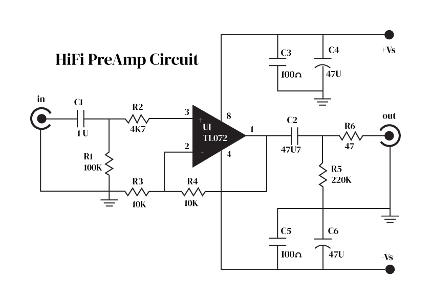
(An example of a preamp circuit diagram using a TL072)
Source: Wikipedia
How to use an Audio Preamplifier Circuit
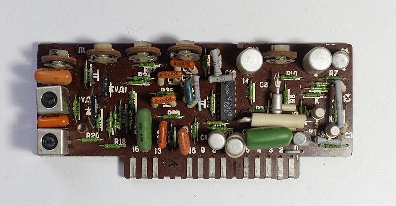
(An audio preamplifier circuit built using an op-amp IC)
Source: Wikimedia
As mentioned earlier, the TL072 is a dual audio op-amp IC. However, a single op-amp uses a default operating voltage of 9V DC.
During operation, the audio input of the circuit receives feedback from the output. As a result, it effectively overcomes external sources of noise. Often, the primary culprit is noise from resistors. There is no distortion, either.
Furthermore, the circuit allows for fine-tuning. For example, to achieve low distortion and input impedance balancing, you adjust the value of R1. Otherwise, you will need to increase the circuit’s input impedance by adjusting R4.
On the other hand, you have R2 and R3 in the circuit. These, in particular, act as negative feedback resistors. And their primary purpose is to measure the output signal. However, tuning the input resistance values too high increases noise production. Alternatively, adjusting them too low causes an increased load on the circuit. Also, it leads to increased distortion.
R6, however, is for emptying or discharging the capacitor C2. In general, the effect is to lessen the overall noise differences.
(A video tutorial on how to build a preamp circuit using TL072 IC)
Conclusion
In summary, the TL072 pinout is a high-voltage operational amplifier using JFET transistors. It is, however, remarkable for its low noise ratio and high slew rates. Other outstanding features include low input offset voltage, low harmonic distortion, and a typical input bias current that is relatively low, as well. As a result, it is ideal for circuits needing high accuracy. However, one of its primary applications is in audio circuits pre-amplification.
So, if you are enthusiastic about DIY electronic projects, this is the right place to be. Contact us to learn further about this IC and other related projects.
