
Wireless communication enables information transfer from one point to another without using a transfer medium like an electrical conductor. An example of wireless technology is radio waves with varying frequencies like 433MHz.
433Mhz is a low-energy wireless radio band. How do 433 MHz-compatible devices work, and why choose this technology over standard Z-Wave and Zigbee?
Stick around to know more.
Contents
- 1 What is 433MHz?
- 2 What makes up a 433 MHz Connection?
- 3 433mhz RF transmitter and receiver modules
- 4 Application of 433.92 MHz
- 5 Advantages and disadvantages of 433.92 MHz
- 6 433 MHz Setup Tutorial: connect RF transmitter and receiver to the Arduino UNO
- 7 How to improve the range of the 433MHz RF module?
- 8 Conclusion
What is 433MHz?
433MHz is a wireless radio band commonly used in compatible household devices to send signals.
In addition, one 433 Mhz RF system comprises a receiver and transmitter that receives and sends radio signals between two devices. Also, it benefits innovative applications like wireless doorbells, garage doors, home automation, access control, etc.
What makes up a 433 MHz Connection?
A 433MHz connection has three types of devices enabling communication: a transmitter, receiver, and transceiver.
433mhz RF transmitter and receiver modules
Here, we will introduce typical 433mhz RF transmitter and receiver modules.
First, we have a transmitter that relays information over an RF of 433MHz despite limited bandwidth limitations.
Then, there’s a receiver module that listens to and receives commands.
Lastly, the transceiver offers the capability of sending and receiving signals, therefore, acting as a transmitter and receiver.
433MHz RF transmitter and receiver pin assignment
Now, let us discuss the pin configuration of the transceiver and receiver modules.
Transmitter
DATA pin – The first pin accepts the digital data needed for transmission.
VCC pin – It acts as the transmitter’s supply power pin. Often, the positive DC voltages range from 3.5V To 12V. Again, remember that supply voltage is directly proportional to the RF output in that a higher voltage results in a more excellent range.
GND pin – It is the ground pin.
Antenna pin – It connects to the external antenna. It is advisable to solder a 17.3cm piece of solder wire for increased range in the plug.
Receiver
VCC pin – It is the power supply of the receiver. Contrary to a transmitter, 5V is recommendable for the receiver.
DATA pin – It functions as the output of the digital data received. Since there are two internal center pins tied together, you can choose one for the data output.
GND – It acts as the ground pin.
Antenna – Despite being unmarked, it operates as an external antenna. It is next to the small coil at the lower left of the radio module. Similarly, it’ll need a 17.3cm soldering wire for augmented range.
Specification and Features
Transmitter
They include;
- First, it has a transmission range of 90m in open space and a velocity of less than 10Kbps.
- Then, its frequency error is a maximum of +150kHz with a transmission power of 25mW and current output of 500mA peak.
- Thirdly, its working frequency is 433.92MHz, while its modulation mode is ASK (Amplitude Shift Keying).
- Its resonance mode is (SAW). It also has a working current of a minimum of 9mA and a maximum of less than 40mA.
- Also, it has an IF frequency of 1MHz, a maximum transmission rate of 300K, and a typical sensitivity of 105Dbm.
- Lastly, its working voltage ranges (mains voltage) from 3V to 12V.
Receiver
They are as follows;
- A sensitivity exceeds -100dBm (50Ω) and a bandwidth of 2MHz.
- Secondly, its working frequency is also 433.93MHz but its modulation mode can either be ASK or OOK (Of Hook Keying).
- Besides being popular and cheap, it also delivers an output to the data pin in an encoded form.
- You can change its frequency using the available node.
- Also, it has an IF frequency of 1MHz and a typical sensitivity of 105Dbm.
- Finally, its working current is a maximum of ≤5.5mA while its working voltage is 5.0VDC +0.5V.
Working Principle
Transmitter work
The transmitter module functions at 434MHz and uses ASK (more convenient than Frequency shift keying).
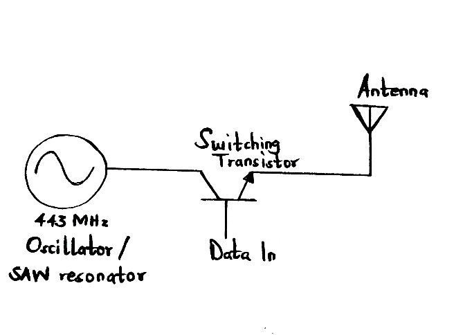
433MHz transmitter module working
- First, it passes a serial input via an MCU, then uses RF to transmit the signals.
- Afterward, a receiver module receives the transmitted signals at the other end of data transmission.
- Hence, applying a low logic to the DATA stops the oscillator from generating the RF wave. Conversely, a high sense on the DATA pin enables the oscillator to produce a constant RF output carrier wave of 433MHz.
Receiver work
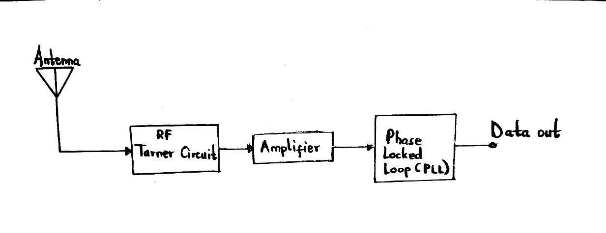
433MHz receiver module working
- It receives signal data (433MHz frequency) before sending it to the data pin in an encoded form. However, you can use a variable node to adjust/change the frequencies from 315MHz to 433MHz.
- A decoder or microcontroller will later decode and view the data signal.
- Lastly, it has some Op-Amps and RF tuned circuits that amplify the established carrier wave from the transmitter. Next, the amplified signal gets into the Phase Lock Loop before proceeding to the decode. It now produces an output stream with less background noise.
Application of 433.92 MHz
- Government radar devices,
- Amateur satellites,
- Energy machine networking,
- Amateur/Ham radio like DX, Telephony (SSB), Morse (CW), Digital Voice (DV) messaging,
- RFID devices,
- Remote control devices like domestic sensors, wireless switches, remotely controlled blinds,
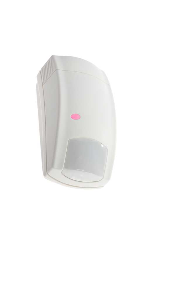
(infrared sensor)
- Wireless instruments, and
- IoT (Internet of Things)

Advantages and disadvantages of 433.92 MHz
Advantages
Some of the pros of 433MHz are;
Consumes low power
Compared to other home automation standards such as Zigbee or Z-wave, 433MHz uses relatively low power. Thus, it is ideal for battery-operated devices like buttons or wireless sensors.
A long wireless range
Secondly, its benefit over infrared in the remote control is that walls can’t block it since it’s a radio technology, for nothing will obstruct the radio signal instance, when you’re in a different part of the house but controlling a motorized roller signal.
Furthermore, it has a lower frequency compared to Wi-Fi (2.4/5.8GHz), Zigbee (2.4GHz), or Z-wave (868-928 MHz). It means its point-to-point frequency range of 433MHz is a significant feat.
Cost-effective
Manufacturers find these devices easy to implement in intelligent home products, which explains why they sell quickly and faster.
Disadvantages
The cons to consider before purchase include;
Receiver/Transmitter required
Unfortunately, 433MHz won’t have direct communication with your PC or phone since they lack a dedicated antenna. However, it possesses similar features to premium standards, e.g., Z-Wave and Zigbee.
Lacks Mesh Networking
Generally, mesh networking permits devices to relay signals intended for other network nodes when working under a similar technology. In addition, if you add more nodes, your network’s reliability improves.
Sadly, 433MHz devices can’t construct a mesh network. In this case, we recommend Z-wave or Zigbee since they have the feature.
Isn’t so smart
433MHz technology is bare/minimal as it has a one-way signal (receiving or sending). Consequently, you’ll have to assume it has picked a call and executed it since it does not confirm the signal commands. Some devices, particularly sensors, can be less dependable than Z-Wave and Zigbee standards.
Moreover, the devices under the 433MHz module don’t give any information on their energy consumption or battery status. And so, you’ll need to check the battery voltage level using an analog pin.
433 MHz Setup Tutorial: connect RF transmitter and receiver to the Arduino UNO
Let us now work on a project using the charger-compatible 433MHz.
Required components
- Battery holder,
- Jumper wires,
- Power bank,
- Small breadboard,
- 1.8″ Color TFT,
- DHT22,
- 433MHz RF kit, and
- Cheap Arduino UNO
Transmitter diagram
The pin connections between the components and Arduino are as follows;
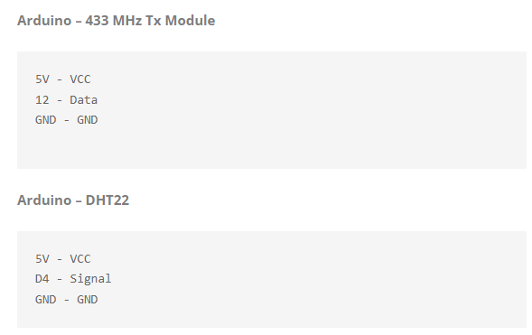
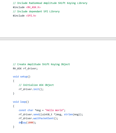
Arduino code — for 433MHz RF transmitters
Below is a summary of the receiver code using the Arduino IDE interface.
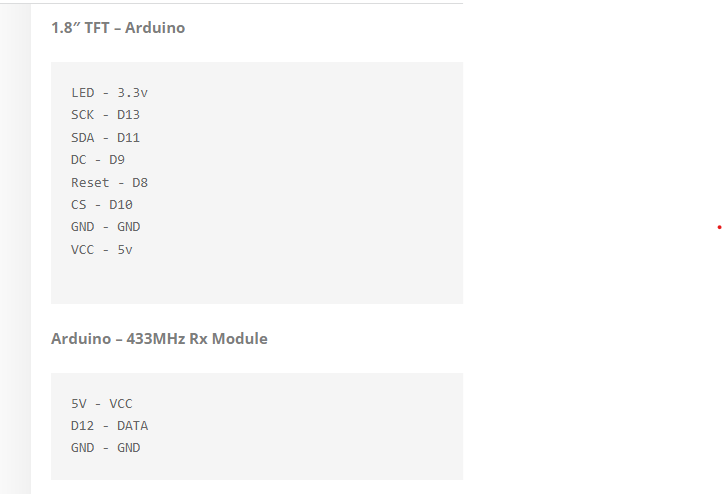
Receiver diagram
Pin connections are in the display below;
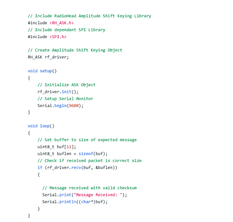
Arduino code — for 433MHz RF receivers
Below is a summary of the receiver code using the Arduino IDE interface.
How to improve the range of the 433MHz RF module?
The receiver and transmitter antenna greatly influence the range obtained with the two RF modules. You would communicate over a 1m distance without the antenna.
In open spaces (outdoors), you can communicate over a 50m distance with an excellent antenna design. However, indoor signal ranges will be a little weak.
A simple piece of the single-core wire is enough to build a proper antenna for the receiver and transmitter, so don’t complicate it. Also, maintain the antenna’s length since the diameter is not as significant. An efficient antenna is similar to the wavelength you use it for then. A quarter-wave antenna is better.
Calculating the wavelength of a frequency is denoted by;

Practical application in the air;
Speed of transmission = Speed of light (i.e., 299,792,458 m/s)
Transmission frequency = 433MHz
Therefore;

As we’ve seen, a 69.24 cm (rounded off to 70-centimeter band) antenna is extended and impractical. Thus, a quarter-wave helical antenna of approximately 6.8in or 17.3 cm is idyllic.
Conclusion
Briefly, the Radiofrequency (RF) 433 MHz band is a cost-effective radio device with low-energy networking and wireless capability.
We do hope that you’re now a day wiser on 433MHz devices. However, if you still have questions, you can contact us.