One can say that the 555 Timer is one of the most common chips used in DIY electronics today. They are small, practical, and easy to use once you better understand how they work.
Below, we will share with you what a 555 Timer is and give you an in-depth understanding of their electronic theory as well as the principles of circuits.
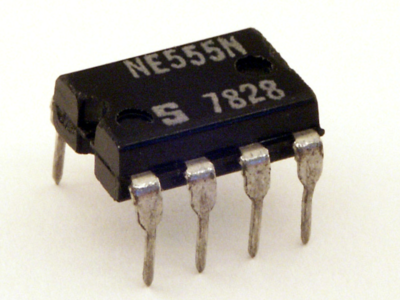
(The original 555 type oscillator)
Contents
1. What is a 555 Timer?
The 555 one-shot timers get their name from the three internal Five-k Ohm resistors used to generate the reference voltages for the two comparator circuits. One of the most popular and valuable precision timing devices on the market can be helpful as either a simple timer or for generating single pulses and long-time delays.
People use these timers in basic electronics for a long period of time.
2. 555 Oneshot circuit– 555 the Timer Block Diagram
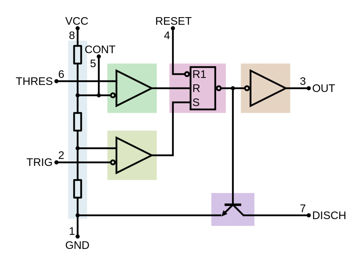
( A 555 Internal Block Circuit Diagram)
- Pin One: This is the ground pin as it connects the 555 timers to the negative supply rail.
- Pin Two: These pins are also called trigger pins. In response to a negative pulse on this pin, the internal Flip-flop switches from a “LOW” state to a “HIGH” state when the voltage falls below one-third Vcc.
- Pin Three: This is our output pin. The ‘driver’ of any TTL circuit is the output pin, as it can sink or source up to 200mA. Your input trigger pulse is shorter than your output pulse.
- Pin Four: The Reset pin. Pin four helps to reset the internal Flip-flop that controls timing output (pin three). Generally connected to logic “1” level when not in use, this input is an active-low input.
- Pin Five: This is the pin that controls the voltage. The override level of the voltage divider network is 2/3Vcc. The voltage applied to this pin can change the width of the output signal independent of the RC timing network. A 10nF capacitor connects to pin one when not in use to ensure there is no noise interference.
- Pin Six: This is the threshold pin. Upon reaching a voltage exceeding 2/3Vcc, you reset the Flip-flop, and the output switches from the “HIGH” to “LOW” state.
- Pin Seven: Also known as the discharge pin. When the output voltage, pin three switches low, the capacitor discharges to the ground through the Collector of the internal NPN transistor.
- Pin Eight: This is your supply and Vcc pin. It is the pin that supplies power, which for general-purpose 555 timers has a supply voltage between 4.5V and 15V.

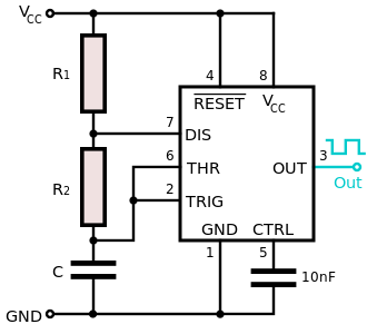
3. 555 Oneshot circuit– The Monostable 555 Timer

(Diagram of a monostable multivibrator Circuit)
The flip-flop changes its output from a “LOW” to a “HIGH” state when a negative pulse applies to the trigger input, also known as pin two, of the Monostable Timer circuit. By removing the short circuit across the external timing capacitor, you turn off the discharge transistor connected to the discharge pin. This eliminates the short circuit and has noise immunity. Direct current, as well as alternating current products, contain them. Did you know that the AC electrical circuit is the fundamental relationship between voltage, current, and resistance in an AC circuit?
In other words, this process allows the timing capacitor to charge up via the resistor. Until the voltage reaches its threshold, dictated by pin six, the output of the comparator goes from a ‘HIGH’ state, and turns the transistor ‘ON,’ and discharges the capacitor via the discharge pin.
There are currently two open, working circuits on the Monostable Timer. The output wants another trigger pulse to restart the timing process once again once the output returns to a stable state, ‘LOW.’ Essentially, this means that there is only one stable state for the Monostable Multivibrator at this exact time.
4. 555 Oneshot circuit–The Monostable Circuit Equations

( The equation for a monostable timer)
‘T’ is the length of the electrical output in seconds
‘R’ is the resistance of the resistor in Ohms
‘C’ is the capacitance of the capacitor in Farads
As you can see in the equation above, you can increase the electrical output by using larger resistors or capacitors that can handle a lot more electricity running through them. You are also able to shorten the equation as well. Use smaller capacitors and smaller resistors for a smaller electrical output.
( 555 Timer With Arduino Top View Illustration)
Let’s say, for example, you have Pin one and Pin three connected to an LED in between both pins. This means that the current will sink or absorb into the 555 timer output terminal. The LED will be on, and the output will be ‘Low.’
In another circuit, you have Pin three and your ground pin that connects to your LED. This will mean that the current will Source, or supply, into the output terminal. The LED will be on when the output is ‘High.’
It is possible for the 555 timers to sink and source output load simultaneously. This reaction will result in both LEDs being connected to the same output terminal simultaneously, and they will turn on simultaneously. In other words, you have the power of an additional circuit, but you only use one current circuit.
Final Thoughts
A 555 One-shot circuit has a one-shot pulse. The timer circuit is the heart of the circuit. In the circuit, you will also have a Relay Switch. The Relay connects to the output of the IC. You can then connect any AC electric circuit or DC electric circuit appliance to your one-shot timer circuit.


