
Contents
Characteristics of 556 circuits
A 556 circuit is an integrated circuit used as a timer IC. What makes this chip unique from others is its different operating modes: dual-timer mode or single-timer mode with the flip of a switch. It has characteristics such as:
- First, it contains two separate 555 timers, one with an adjustable pulse width and a preset output pulse.
- Second, these 555 circuits are wired in series, which means they share the same clock input (IC).
- Third, this IC also includes useful features like low power consumption and low supply voltage operation. Importantly, this allows you to connect many different electronic components without worrying about the circuit breaking down.
- Also, it has an adjustable duty cycle.
- Finally, its mode of operation can either be in astable mode or monostable mode, depending on your choice.
556 Pin Configuration and Connection
A critical part of understanding 556 circuits is also knowing the connections. 556 chips have two sets of 555 pins that are both in parallel with each other. The first set of pins is the power supply pin (V+), ground pin (V-), and output-enabled pins (threshold voltage adjuster). Additionally, these pins ensure enough voltage for the circuit’s operation and grounding it to operate correctly.
Pin Description
Pin 2 and 12: used as gateways where timing intervals end.
Pin 14: controls the +Ve supply voltage (range 3-15v)
Pin 4 and 10: for resetting the timing interval period in dual timer mode
Pin 7: Ground(0 Volts)
Pin 3 and 11: adjust the pulse width in dual timer mode through the voltage divider. Also, functions as a reset input when in single-timer mode.
Pin 6 and 8: trigger pin input from either an external/internal clock source to start the timing interval process.
Pin 1 and 13: as output once there is a signal on the reset lines. Also, they are capable of discharging a capacitor between intervals.
Pin 5 and 9: the output pins in dual timer mode. Importantly, these pins connect to other components that need their voltage or currents to be switched on or off.
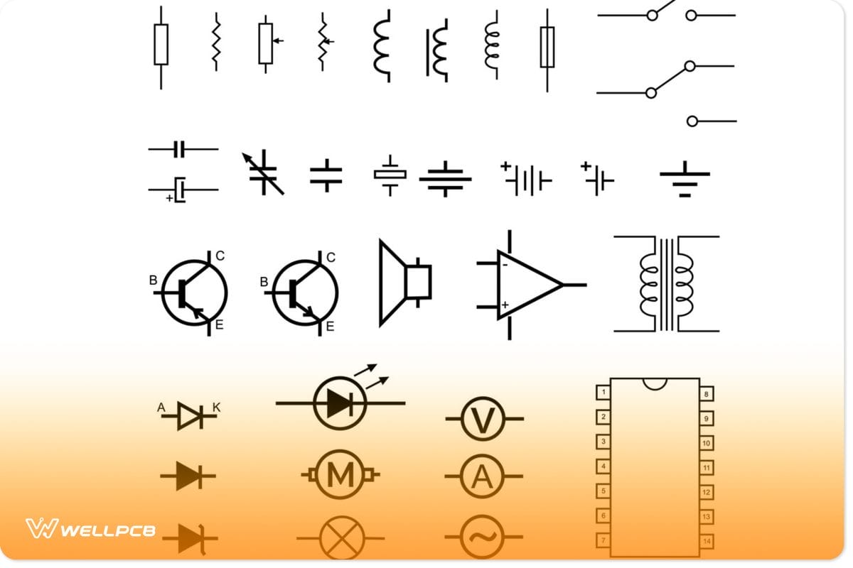
(Electronic symbols)
One crucial aspect of 556 circuits is knowing the pins used for inputting signals into the circuit while others function as outputs. Consequently, this allows you to quickly troubleshoot and fix any problems that may occur with the course!
556 circuits can be set up in many different configurations depending on what each project needs. These include:
- Single timer mode.
- Dual adjustable pulse generation width timers (both 555’s run off of a common clock input).
- Dual fixed pulse width timers (both 555’s have independent control inputs that disable when the common clock is high/low).
- Two separate adjustable pulse width timer circuits.
Different configurations allow you to use 556 circuits for other applications, including oscillators, timing functions, power-saving features, etc.!
(Electronics Engineer at work)
556 Circuit Applications
The application areas of 556 circuits are;
- Electronic ballasts for fluorescent lighting
- PWM (Pulse Width Modulation)
- Voltage-controlled oscillators (VCO) for accurate time delay production
- Power supply circuits that require larger currents/voltage to be switched on or off
- Timers to turn circuits on and off at a specific time
- Used in the linear ramp generator
How to Make a Simple 556 Circuit
When you connect two 555 timer circuits in monostable mode, you get a 556 circuit. Importantly, with the first 555 timer, connect its output pin to the trigger pin of the second 555 timer, as shown below.
Basic circuit diagram of 556 circuits.
Next, we need to find how many pins we’ll need for the inputs and outputs of our circuit. It is so that we can connect it accordingly!
(Electronic components)
Here are the pin configurations for making the circuit;
– Pin FOUR is the reset pin
– Pin TWO will connect to a resistor and electrolytic capacitor for setting oscillator frequency. The oscillator frequency is how long it takes the chip to time out.
– Pin seven is the output pin, and it will then connect to an LED for us to see how long the timer gets to activate.
– Pin FIVE is the control input options pin. It connects to our external clock source (either a circuit or another 555 timer chip).
– We can use pin 8 to connect the power current. Importantly, you should also note that pins two, four, six, and eight are all internally pulled high.
(Electronic Engineer working)
Connection Steps;
First, align the 2 555 timers that connect to form a 556 timer circuit. Now, layout leads for how you will need them (e.g., power, ground). Next, make connections as how you need it. As shown in the circuit diagram, we need to connect the parts for the 556 circuits we are making.
The first thing is to connect pin four (reset) and ground. Then, we connect pin seven (output) and the external resistor to the ground. After that connection, we attach our capacitor, with one side of it going to the resistor. And the other side to the ground. Lastly, we connect our LED to pin eight (collector output).
Finally, we power the circuit and wait for how long our capacitor needs before turning on the LED!

( Circuit board)
555 and 556 Timer Circuit Differences.
The 556 timer circuit is very similar to the 555 timer circuit in that they both share some characteristics. The similarities are high output impedance, rise and fall time intervals, and high-frequency limits. Moreover, both timers can operate in the timing from the microseconds range at voltages below 5 volts.
However, some differences help 556 timer circuits stand out from 555’s, such as:
| No | 556 Timer Circuits | 555 Timer Circuits |
| 1 | Has the ability to use the output as either a logic-level signal or to sink/source maximum output currents | Unable to sink/source maximum output currents |
| 2 | Are more resistant to electrical noise | Less immune to electrical noise |
| 3 | More versatile with their configurations | Less versatile in configurations |
| 4 | Have low input impedance | Have higher input impedance |
| 5 | Adjustable pulse width control in both timer circuits | Only used for generating a single pulse |
| 6 | Chips have additional pins used as reset input/outputs. Helpful when the clock input or functioning does not control them as an enable pin. | Has fewer pins, hence limiting its usage. |
Summary
556 circuits provide excellent characteristics that make it an easy-to-use, reliable electronic component. Moreover, they have a lot of different applications that can be useful for hobbyists and enthusiasts alike.
We’ve discussed some key aspects of 556 circuits. But if you want to know more, feel free to reach out with any questions or concerns. Happy building!


