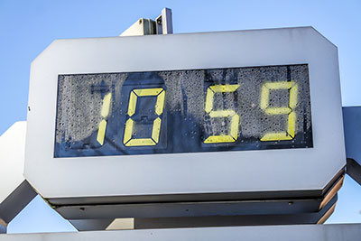
If you have observed a clock timer counting digits from 0 to 9 and back to 0, you have probably seen a 74LS93 IC operation. Notwithstanding, there are other pulse-generating ICs like the 555-timer. However, the 74LS93 pinout is the preferred IC for several reasons.
One of which is that microcontrollers are not suitable for certain electronic projects. For that purpose, the 74LS93 serves as an excellent alternative. Overall, if you need to create timer applications, you are where you should be. Eventually, you learn how the IC works and how to use it.
Contents
1. The 74LS93 Pinout Configuration
Below is a description of the 74LS93 pinout configuration.

2. 74LS93 Features and Specifications
The following are some unique characteristics of the 74LS93 pinout. The first is that the IC uses a 4-Bit Binary Counter. Typically, the operating voltage is 5V. However, the standard operating voltage range of the IC is between 4.5V and 5.5V. The output HV (high voltage) is 3.5V. Meanwhile, the output LV (low voltage) is 0.25V. On the other hand, the output HC (high current) is -0.4mA. While the output LC (low current) is 8mA.
Furthermore, the corresponding CLK input frequencies, CKA input (CP1) and CLK B input (CP0) are 16MHz and 32MHz. Alternatively, the input count pulses of CP1 and CP0 are 30nS and 15nS. Finally, you will find the IC available in 14-pin PDIP, PDSO, and GDIP packages.
3. What is 74LS93 IC?
First of all, the 74LS93 is what we call a 4-bit counter. The IC consists of a mod-8 counter and a mod-2 counter. As a result, you get a four-bit output counting in binary from 0 to 15.
Generally, the 74LS93 pinout is compatible with TTL-based systems and microcontrollers. Also, it is available in several different 14-pin packages like SMD, DIP, and so on.
4. How does the 74LS93 Digital Counter work?
The 74LS93 digital counter IC is simply a series of JK flip-flops. Therefore, these four flip-flops operate on the principle of pulses. Typically, we use a timer IC or microcontroller to provide these input pulses. But, the 74LS93 pinout offers similar functionality with its four output pins, two clock pins, and two reset pins.
The digital counter input circuit consists of two different parts; the MOD 8 counter and the MOD 2 counter. The MOD-8 counter consists of three JK flip-flops, each receiving the output of the previous JK flip-flop counter.
Alternatively, the MOD-2 counter reads 0 and 1. Typically, these readings occur when the input clock pulse changes from a LOW to a HIGH state and vice-versa. As a result, the MOD-2 output then goes to the initial JK flip-flop clock pulse of MOD-8. In total, the whole JK flip-flop outputs make up the four-bit counter.
(An explainer video on the 74LS93 IC).

5. How to use the 74LS93?
To use the 74LS93 IC is pretty straightforward. The first step is to power the IC via the VCC pin and the ground pin with a +5V voltage supply. Also, using the MR (Master Reset) pins, it is possible to choose a preferred mode. Typically, you connect the two Master Reset pins to the ground (LOW).
Further, let us understand how to use the 74LS93 IC with specific circuits. Therefore, some common circuit examples involve the digital counter IC.
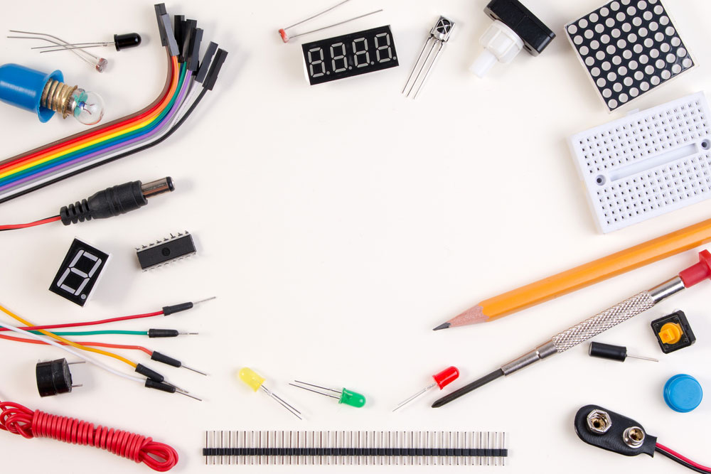
(A set of circuit components needed to build microcontroller-related projects).
74LS93 As A Single Digit Counter
To effectively build this circuit example, you need a 74LS93 equivalent like the 74LS20 with four-input NAND gates. Also, it would help if you had a 74LS04 with three NOT gates. With these, you can design a single-digit counter using a BCD seven-segment display. In other words, the decimal counter reads from 0 to 9.
However, the 74LS93 4-bit decade/binary counter allows 16 binary counts. Still, the counter needs a reset each time the binary digits count to 9. Else, the output on the 4-bit BCD counter displays a random message.
So, to reset the single-digit counter, you need a feedback reset circuit. And to build such a circuit, you need combinations of output from a NAND gate and NOT gate.

(An example of a digit counter using LED display).
74LS93 As A 2-Digit Counter
In this example, the 2-digit BCD counter displays values like 00 up to 99. It gives a similar logic output to the single-digit BCD counter circuit.
In this case, however, the initial BCD 7-segment display increases in value on a condition. And that increment comes when the second BCD 7-segment display receives a clock reset signal.
6. 74LS93 Equivalents
Some equivalents for the 74LS93 pinout are
- 74LS192
- 74HC19
Other Alternative ICS
There are alternative ICs that function just like the 74LS192. They are
- CD4017
- CD4020
- CD4022
- CD4060
- 74LS90
- 74LS02
7. Applications
The 74LS93 pinout IC is a crucial part of many circuit operations. Some of its famous applications include
- For creating periods with long timing.
- Generally, the IC is useful in applications requiring timing.
- It is vital in pulse counter circuits and a frequency divider in astable operations.
- The 74LS93 is a good alternative for projects needing counters without microcontrollers.
- Finally, it helps represent numbers on 7-segment displays.
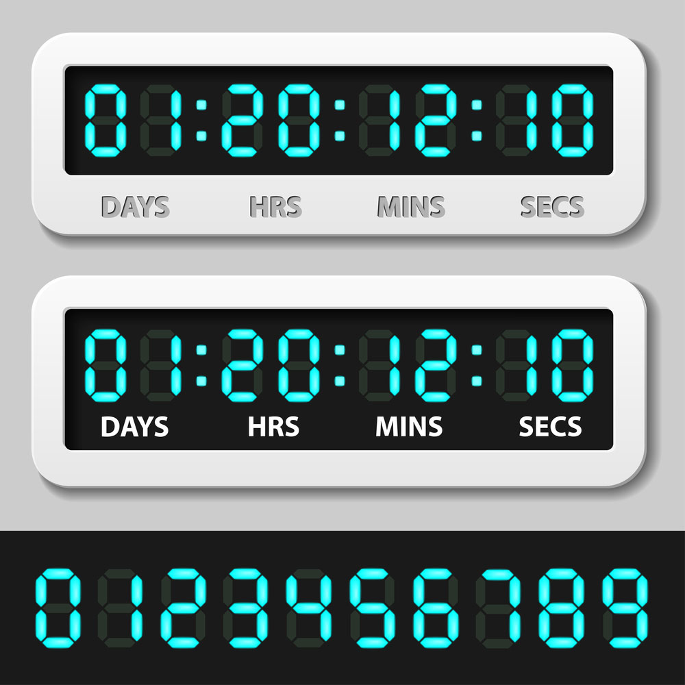
(An application of the 74LS93 in a countdown timer).
Conclusion
Summarily, the 74LS93 pinout is a digital counter IC. It contains four JK flip-flops that enable it to switch logic states from LOW to HIGH clock inputs and vice versa. These changes, in turn, generate clock pulses that are visible on a BCD 7-segment LED display. This IC is standard in digital clocks and timing applications, in general.
Having learned how the 74LS93 IC works, you might want to try out a few applications like those mentioned above. However, if you are not exactly sure what you need to begin with, contact our page for professional assistance.


