Do you need a fixed voltage linear regulator that’s easy to set up and use? Have you heard of the 78XX series of regulators? The 7812 IC is a great voltage regulator in the 78XX series. They may get damaged when you overload or connect them poorly, as robust as they are. Here at WellPCB, we have all it takes to guide you through your project.
But first, read on to find out more about the 7812 IC.
Contents
What is a 7812 IC?
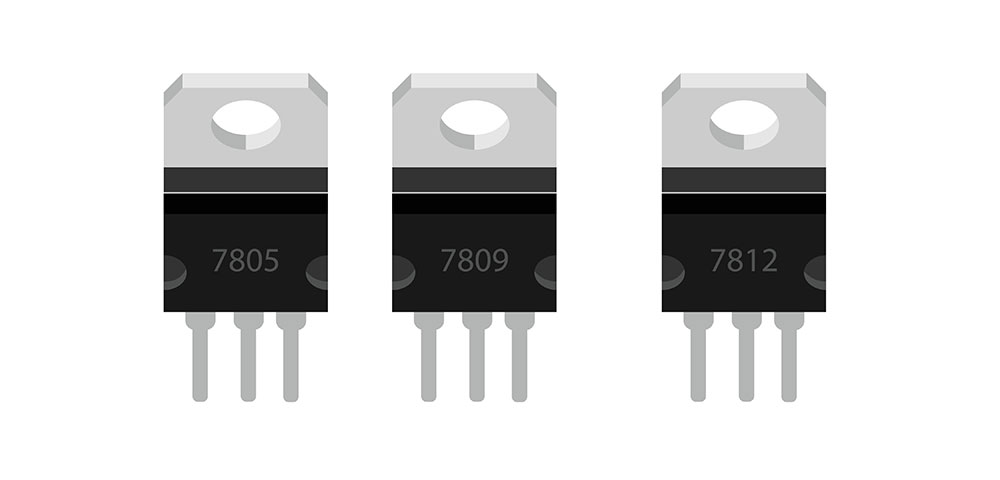
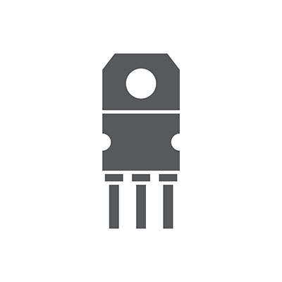
Fig 1: Voltage regulation IC, 78XX regulator family
The 7812 IC is a fixed voltage DC linear regulator that eliminates power distribution problems caused by single-point regulation. It belongs to the 78XX series of regulators and can output 12V at up to 1A. With a good heatsink, the 7812 IC can supply 1A for input voltages from 14 to 35V.
Additionally, it helps with short circuits and thermal overload protection.
7812 IC Pin Configuration
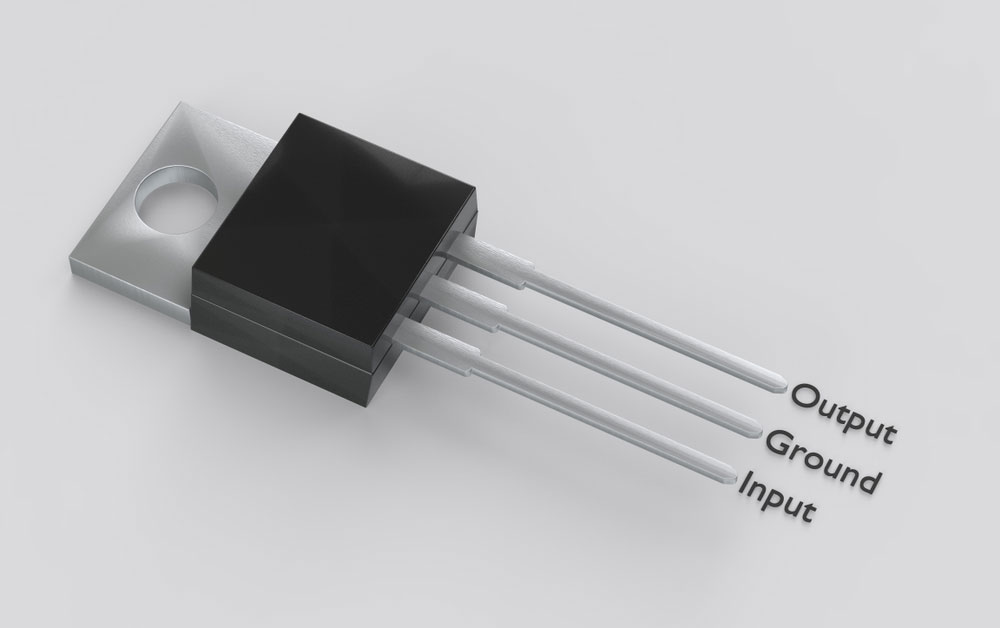
Fig 2: Isolated TO-220 electronic package with 7812 pinout
The LM7812 pinout is as follows:
- Pin 1: Positive input voltage (IN)
- Pin 2: Ground (GND)
- Pin 3: Positive output voltage (OUT)
The 7812 pinout is relatively straightforward and enables it to generate positive voltages concerning the Ground. If you’re working on a circuit that needs both positive and negative voltages, add a 79XX family IC.
The 79XX family ICs must correspond with their 78XX family counterparts. For example, you can only use a 7812 IC with a 7912 IC to produce positive and negative 12V output.
Features
- First, the IC has an input voltage range of 14 to 35V
- Second, it has a 12V fixed output voltage
- Third, the 7812 has a 1A continuous current and a surge capability of 2.2A (peak current)
- Fourth, it’s a TO-220 package IC
- Fifth, it has a 2V dropout voltage

7812 Voltage Regulator Circuit
Circuit Diagram
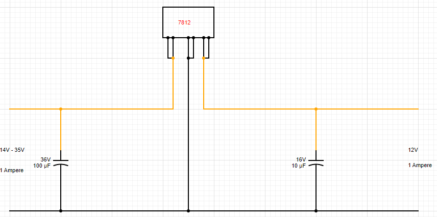
Fig 3: 7812 voltage regulator circuit diagram
Components Needed
- 14 to 35V DC supply at 1A
- 10uF/16V and 100uF/ 36V capacitors
- 7812 IC
- Soldering iron and connecting wires
- Breadboard or Veroboard
Circuit Explanation
- To begin, place the 7812 IC on the VEROboard or breadboard.
- Connect pin 1 (Positive Input Voltage) to the positive input supply.
- Next, connect pin 2 (Ground) to the negative input supply.
- Connect the 100uF capacitor between input pins 1 and 2 (positive input and Ground).
- Also, connect the 10uF capacitor between input pins 2 and 3 (ground and positive output).
- Attach the positive terminal of your measuring device (multimeter/ voltmeter) to pin 3.
- Attach the negative terminal of your measuring device (multimeter/ voltmeter) to pin 2.
- Power your circuit, and see if you’ll get 12V.
Power Loss in 7812 ICs
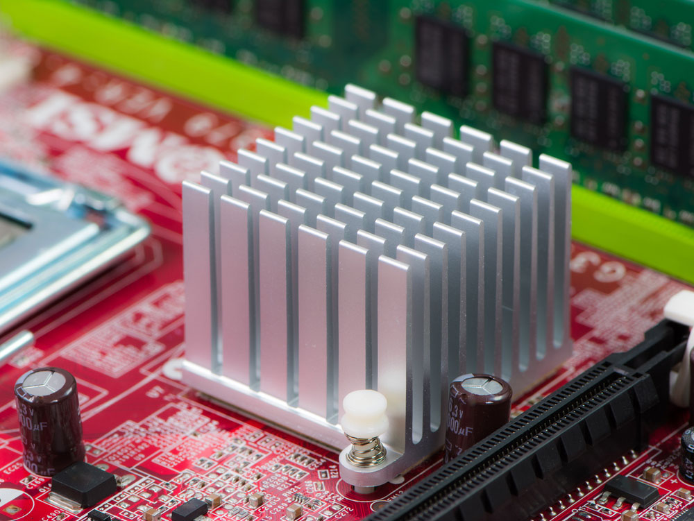
Fig 4: Silver heatsink on a computer motherboard
Linear regulators play the same role as the DC-DC converters but dissipate more heat. The higher heat dissipation results from the series pass transistor dropping excess voltage. The linear regulator’s power dissipation depends on the variation between Vin and Vout and the current drawn. The more significant the difference between Vin and Vout, the higher the circuit’s power dissipates. As a result, it will limit how much current you can draw from the device.
Power Dissipation = (Vin – Vout)* Iout
Let’s take our 7812 IC Vin to be 15V at a current of 1A. The power dissipation will be:
(15V-12V)*1A = 3W.
Your 7812 IC TO-220 device has to dissipate 3W of power. However, under typical conditions, the device can dissipate a maximum of 1 to 1.25W without a heat sink. Our circuit needs a heat sink with a 300-350mA maximum output current that will run at 85-95°C.
Applications

Fig 5: A remote control car
Conclusion
As much as the 7812 is a reasonably robust IC, we still need to be careful while using it.
Finally, contact us for any project materials, comments, suggestions, or gray areas that need clarification. We’ll get back to you as soon as possible.


