
Contents
What is an FM Transmitter Circuit?

A portable FM Radio
An FM (Frequency modulation) circuit represents wireless communication enabled by a BJT or a single transistor. Sound signals in this circuit travel by shifting the carrier wave frequencies depending on the prevailing message signal.
FM transmitters operate at a very high carrier frequency and output frequencies of between 87.5 HZ to 108 MHZ. Also, the FM transmitter will deliver excellent sound volumes at a relatively low electric power input.
Lastly, as earlier captured, an inductor and variable capacitor are two of the essential components of the circuit.
FM Transmitter Circuit Principle

An FM transmitter radio receiver
FM transmission happens in three main steps, namely:
- Audio pre-amplification
- Modulation
- Transmission
An audio amplifier facilitates the audio amplification process, which is critical in applications such as phone conversations. Next, a variable frequency oscillator circuit takes over the modulation and the subsequent carrier signal generation.
Further, a power amplifier boosts the FM signal strength to realize a low impedance output that matches the external antenna’s.
A small RF Transmitter is Built Around a Single Transistor.
An FM radio frequencies
We’ll illustrate a wireless FM transmitter circuit featuring an RF transmitter on a transistor. Primarily, it operates as a stable oscillator with a tank circuit to enable the generation of the necessary oscillating frequency.
Check out the circuit diagram and parts list.
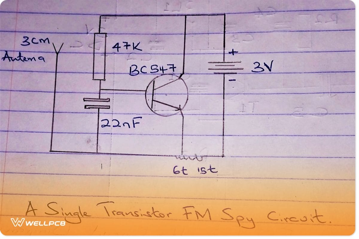
Circuit Diagram

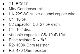
Parts List
The minimum components for this simple circuit are as follows
Entire Circuit Overview
First, this is a single transistor FM spy circuit with drawbacks such as the following:
- It lacks a wide transmitting range and lacks an enhanced sensitivity range
- Also, It requires 1.5V to function. It limits its overall capabilities.
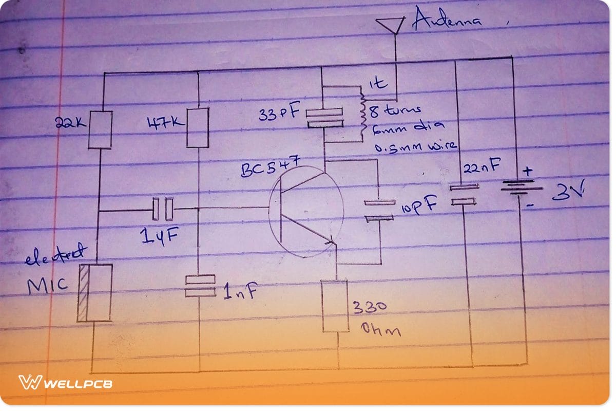
Hence, an extra transistor and dynamic microphone can significantly improve the circuit’s performance. The system transmits electromagnetic waves in the 88-108 MHz range.
Single transistor FM spy circuit
The circuit diagram below represents this circuit.
Incorporating Q Factor
Circuit diagram
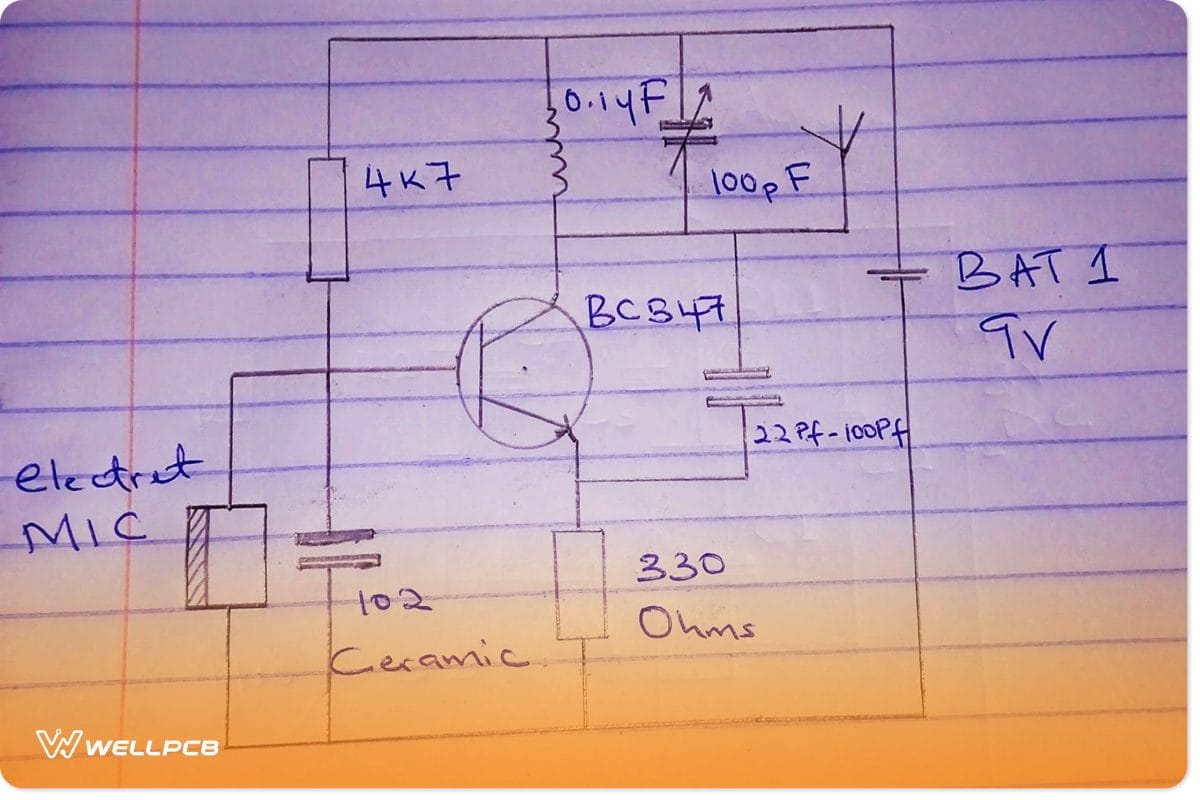
Featuring a Q factor, the circuit can produce a high bias voltage. During assembly, ensure you connect the capacitor to the coil to improve the system’s performance.
Given the attribute of this circuit, it is common in power transmitter systems that need a maximum range transmission.
Better Saturation Capability
This FM transmitter design is a common emitter type rather than a base such as the above circuits. Primarily, it features an inductor at its base to improve the saturation capability. In turn, this improves the performance of the transistor.
Also, it gives an impressive transmission range and the most precise sound reception, especially with good microphone sensitivity.
Adjustable Coil Slug
Circuit diagram

It features a slug-based variable inductor, thus making it superior to the previous designs. Accordingly, the inductor adjusts the transmitter by moderating the slug core.
Arguably, this design is the best regarding emotional quality, sound quality, and transmission broadcast range. But, it is likely to have stability issues though you can improve that by minor tweaks to its design to obtain the clearest reception of sound.
FM transmitter circuit diagram: Improved Stability
Circuit diagram
You can significantly improve the circuit’s stability by tapping the wire antenna/ standard TV antenna from one coil’s turn. It happens in two main ways.
- First, the design isolates the wire antenna from the transistor’s collector. In turn, this frees it up by alleviating the load.
- Secondly, isolating the wire antenna improves the functioning of the voltage output of the system.
FM transmitter circuit diagram: Transmitting Music
Circuit Diagram
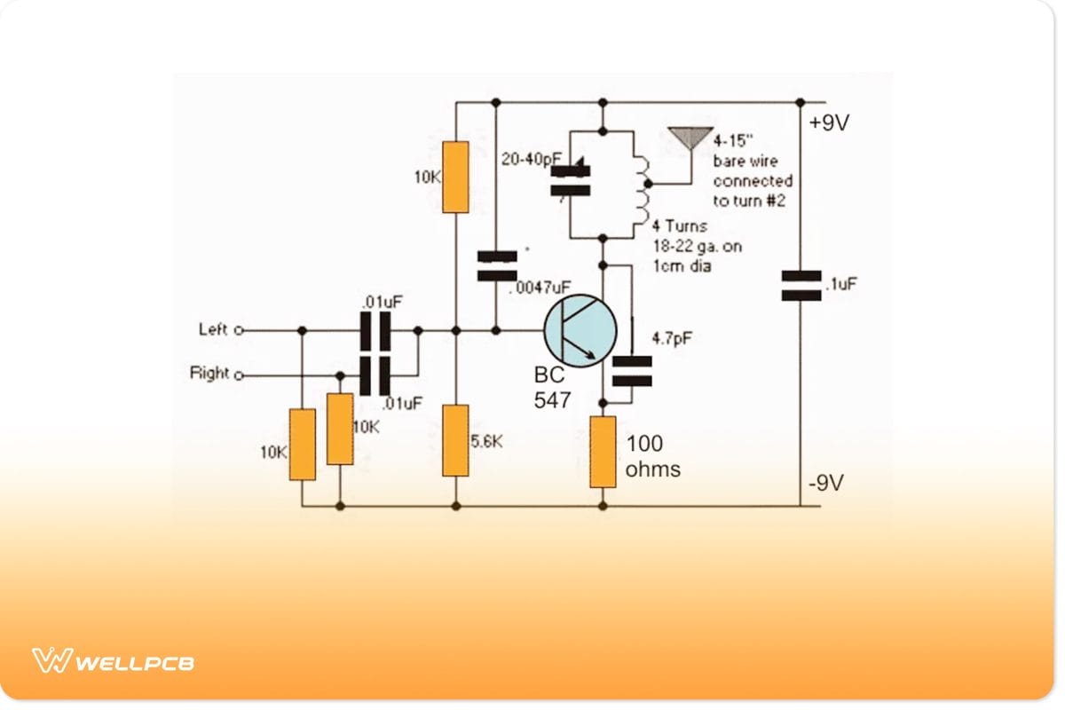
You can also model the transmitter circuit to transmit music. Primarily, this enables the simultaneous combination of stereo input from the input source. The design further ensures that the stereo signals from the two channels are on air to realize optimized reception.
IC 741 Transmitter Using Wire Connection
Above, we’ve primarily dwelt on a Wireless FM transmitter. But, it’s also possible to make a wired transmitter whereby the input signal travels in wires to a loudspeaker. Below is the simple circuit diagram.

Notably, the IC 741 is the non-inverting amplifier chip, and it’s responsible for pre-amplifying the audio signal in the pre-amplifier stage.
Also, you can tinker with the gain setting to set the amplifier’s sensitivity. Often, you should set the gain setting at maximum to ensure it can pick out low speech conversations.
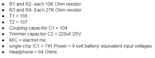
Parts Lists
Some of the critical and passive components of this circuit include the following:
Application Of FM Transmitter Circuit

An FM Mp3 Transmitter
- Useful in transmitting radio signals in wireless components like mobile phone (s), cell phones, amateur radio, and electret microphones.
- Also, its output signal/ audio signal is handy in reducing noise in particular applications such as radio receivers.
- Thirdly, the system is essential in electronic components and sound systems as signal transmitters.
- Lastly, the stereo FM transmitter circuit with a dummy load is handy for educational purposes in portable transmitters and other transmitter modules.
Advantages Of FM Transmitter Circuit
A Vintage FM Radio
- It requires a small component count, such as a satellite receiver, standard FM receiver, wire antenna, and amplifier chip. Thus, it’s easy to create.
- Also, the Broad-Band FM receiver circuit gives an efficient signal transmission range and excellent frequency stability. But it works best as a small-range RF transmitter.
- Thirdly, it’s handy in transmission broadcast demonstrations owing to its easy assembly process. Besides, it allows for frequency adjustment by tinkering with the frequency band.
- With just a simple transmitter, it delivers optimal reception in a few RF stages without necessarily requiring sophisticated parts. Also, it facilitates simplistic frequency variations.
- The power FM radio transmitter can decimate the noise signal via the amplitude variation. It optimizes the frequency output by delivering the exact frequency without losses.
Disadvantages Of FM Transmitter Circuit
- The broadcast transmitter requires an extensive channel range for optimal audio frequencies.
- Also, in this circuit, the broadcast transmitter and broad-band FM receiver strain to operate optimally.
- Besides, the standard FM receiver will receive a low-quality audio signal if there’s medium interference. Also, the clearest reception requires sophisticated parts.
- The circuit is not feasible in high and maximum output power applications.
Conclusion
The circuit is helpful in various ways, as highlighted above. Contact us for additional insights on this transmitter amplifier circuit and its surface mount components.