Perhaps, you have just drawn your circuit diagram, and you wonder how to bring your project to life. There are not many better ways to stimulate your final circuit design than to use a breadboard. But exactly how does a breadboard work?
This prototype board is basically “plug and play.” You only need to insert components and watch it function when set up right – no soldering required. Further in this instructable, you will learn how it works. Also, you get to learn how to connect electronic components to the breadboard to build a simple circuit.
Contents
What is a Breadboard?
A breadboard is simply a plastic electronic workboard for prototype circuits. Circuit designers use a solid 24 gauge wire to connect these circuits on the board. Other times, the breadboard kit uses a variety of colored wires for convenience.
Breadboards are also called plugboards for electronic components. Modern breadboards consist of small sockets in a basic layout of about 0.1 inches each. These sockets allow you to insert component leads or tinned copper wires.
There are long contact rows of holes on both sides of the breadboard for connecting an external power source. Although some types of breadboards have a built-in power supply base, others come in linked blocks fitting for larger circuits.
How Does A Breadboard Work?
In most cases, a typical breadboard has two strips of metal. These are the terminal and the bus strips. In the bus strip, you see two metal clips that run the length of the board. It works to provide the external power supply voltage or VCC in some cases. In others, it serves as the circuit’s ground (GND).
For clarity, the line for supply voltage bears a red mark. On the other hand, the ground is blue or black, depending on the breadboard.
.
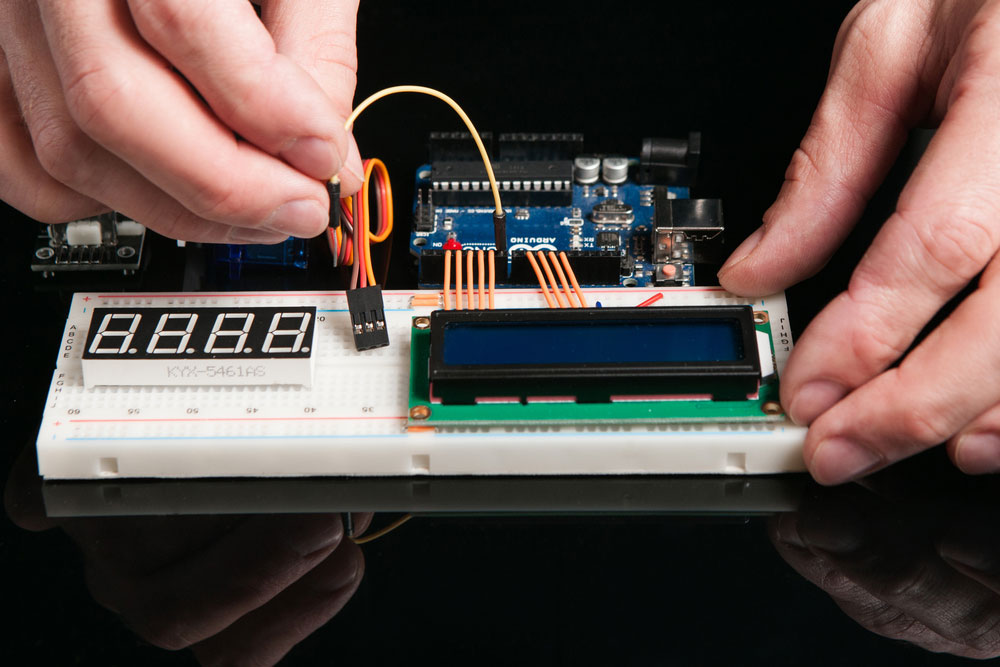
(A circuit builder connecting the Arduino Uno to a breadboard).
The techniques involved in breadboards
The iterative process of circuit building with breadboards allows more flexible testing and simulation. Unlike a printed circuit board, it is possible to change circuit components easily because the board does not require soldering.
Let us take an instance with the amplifier circuit. Generally, the amplifier circuit consists of a broadband amplifier with a high impedance and low input capacitance. In A1 and Q1, we have a path of high frequencies, while the feedback divider gain is between 900Ω to 100Ω. Q2 and A2, on the other hand, form a DC closed circuit. As a result, they combine to reduce the DC offset at the input and output of the course.
Learning to Use the Breadboard
(A short video on how to use a breadboard).

How to use a Breadboard?
The most common way solderless breadboards are used is to construct basic circuits. Therefore, it is essential to assemble the electrical components for your project.
Materials Needed
Other materials needed are
- Breadboard.
- Flexible jumper wire kit.
- 9V battery pack.
- Red and black battery clips.
The steps to follow
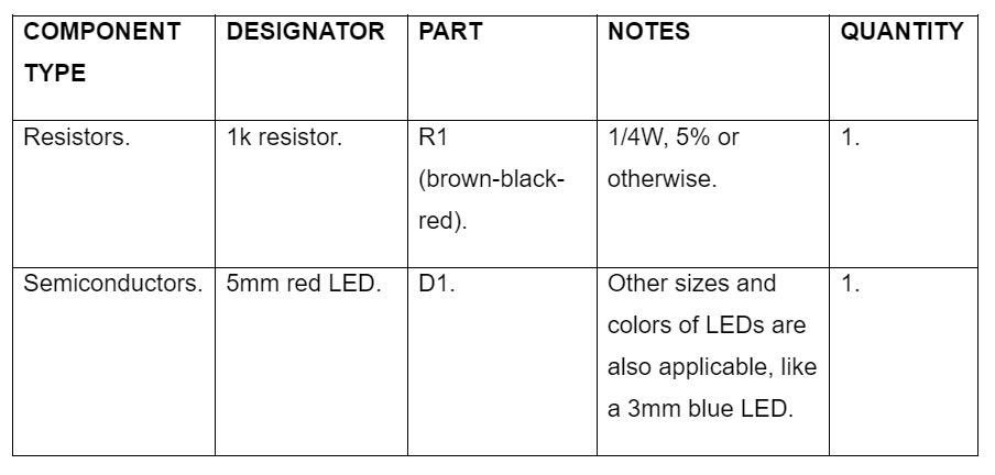
First, you need to prepare the circuit’s power source and other electrical connections. It would help if you connected the battery from its positive terminal (often marked with a red clip) to the 1k resistor. The other terminal of the resistor then goes to the LED’s anode. Similarly, run the LED’s cathode back to the battery at its negative terminal (black clip).
Step 1: Connect the LED by inserting it into the breadboard.
You only need to bend the longer strip of LED metal lead (anode) into the breadboard’s top rail. However, the other end of the LED component legs goes into another socket on the central breadboard.
Step 2: Connect the 1k resistor.
First, bend the resistor metal pins slightly. Then, insert one end into the individual hole below the LED’s cathode lead.
Also, fit the other end into a socket at the center point of the electronics breadboard.
When complete, you have effectively connected the LED cathode and the resistor.
Step 3: Fix the jumper wires.
The next step is to insert a wire link below the lead of the resistor. This connector goes in at the lower rail part of the breadboard.
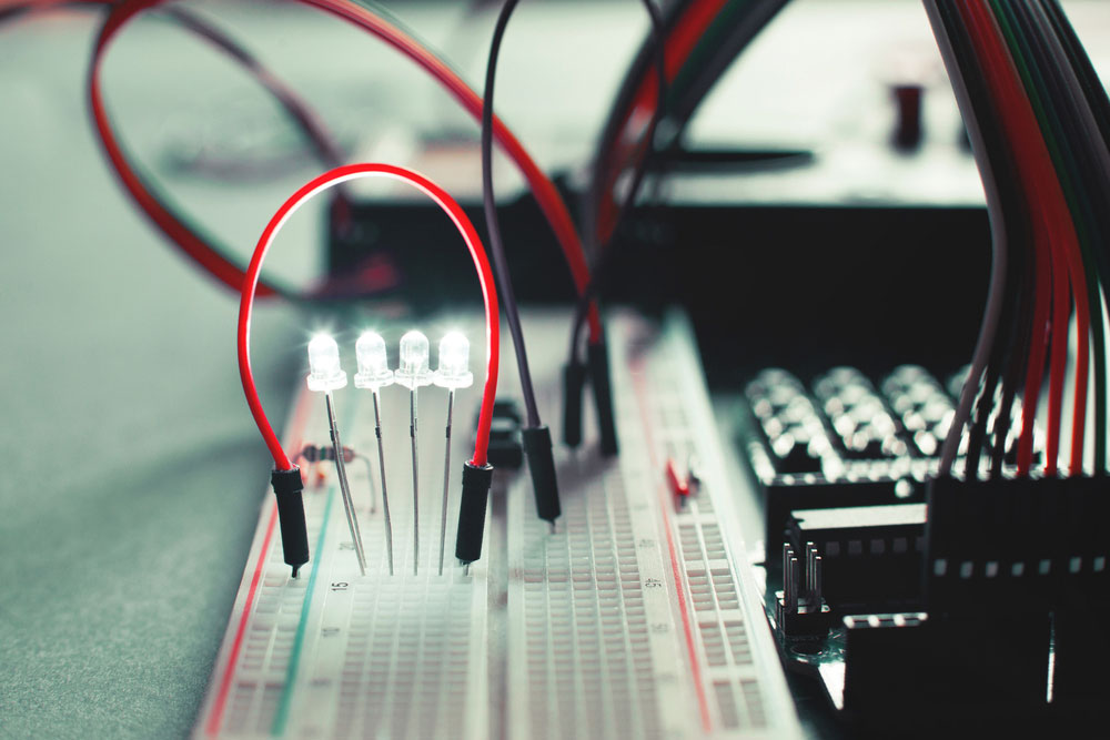
(A close view of LEDs and jumper wires connected to a breadboard).
Step 4: Fix the battery clips on the breadboard.
Do this by plugging the clip’s positive (red) cable into the breadboard’s top rail. Then, connect the negative terminal (black) of the battery clip to the tail part of the breadboard.
Final Step: Connect the battery to the clip.
Finally, connect the battery clip with the battery to supply power to the circuit. If connected the right way, the LED light turns on to indicate. Otherwise, a wrong connection results in reverse polarity and may damage the circuit.
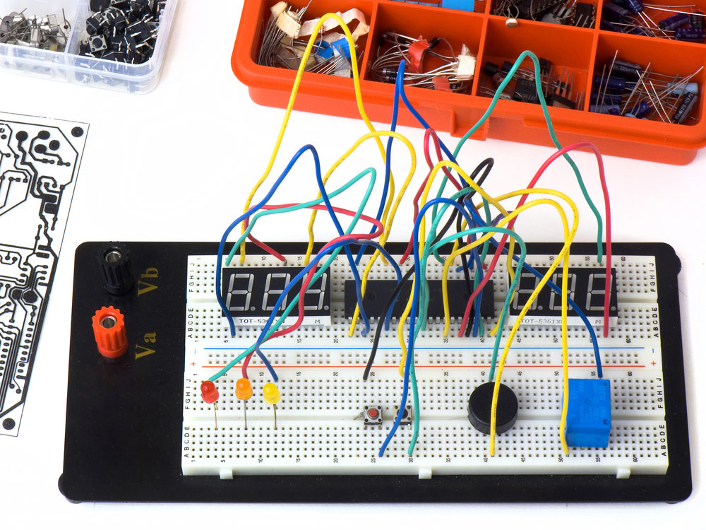
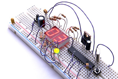
(A white plastic breadboard connected with several electrical components).
Conclusion
In summary, breadboards are test boards for simple and complex circuits. It lets you build temporary circuits and complete electronic projects too. However, it is best to keep your electronic circuit designs simple and easily adjustable using these breadboards.
Besides what we covered so far, you may want to build other complex projects. You may contact our page for assistance with breadboarding any electronic project.


