Pulse width modulation (PWM) is an essential technique in electrical circuit design. It controls power transfer between electrical components by rapidly switching between full and no power transfer. So let’s look at all you need to know about the IC 555 PWM generator.
Contents
What’s Pulse Width Modulation?
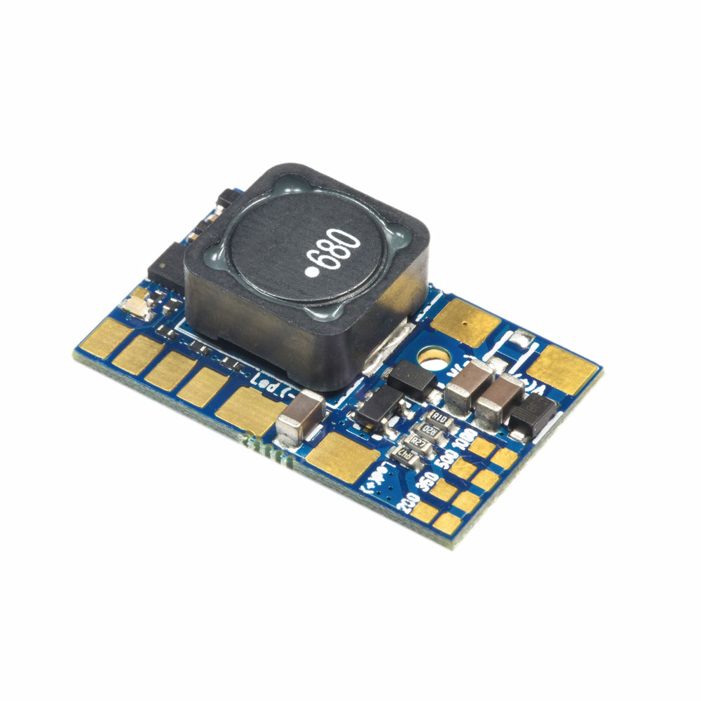
Fig 1: Green Round Led Pulse Width Modulation (PWM) Dimmer PCB
PWM reduces the average power of an electric signal by chopping it up into discrete ON and OFF signals. Therefore, it aids in trimming or dimensioning an output power or voltage of a circuit load per application requirements.
The average voltage will depend on the signal’s duty cycle.

555 Timer PWM Generator Circuit
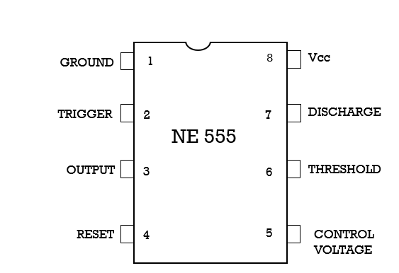
Fig 2: IC 555 Pinout Diagram
IC 555 Timer Astable Mode Circuit Diagram
You can use the IC 555 timer for various circuits, including time delays, pulse generation, oscillation, and pulse width modulation. In this section, we’re looking at its use in astable multivibrators.
A free-running or astable multivibrator oscillator is an oscillating circuit without a stable state.
Here’s its internal circuit.
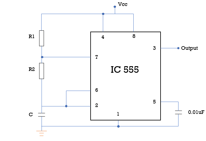
Fig 3: IC 555 Timer Astable Mode Circuit Diagram
Connecting pins 2 and 6 eliminates the need for an external trigger pulse. Pin 4 is the external reset pin that, when not in use, should relate to the Vcc.
Furthermore, filter out the external noise by connecting pin 5 to the ground via a 0.01 uF capacitor. You’ll then form a timing circuit of resistors R1, R2, and R3 to determine output pulse width.
IC 555 PWM using Diodes
IC 555 PWM using diodes works like a standard astable multivibrator with an ON/OFF period output control. The IC 555 uses the properties of the diode network and the potentiometer to determine the ON/OFF period.
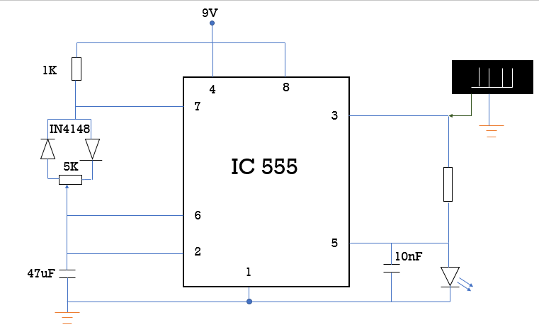
Fig 4: IC 555 PWM using Diodes
First, you’ll start by connecting the circuit, as shown in the diagram above.
The ON time is the time taken to charge a circuit capacitor to 2/3 of Vcc. Similarly, the OFF time is the period for the capacitor to discharge to below 1/3 of the Vcc.
And, here’s how you can set the ON/OFF time of the circuit
First, the ON/OFF time can be set independently or fixed through bifurcating diodes and a potentiometer. The suitable side diode divides the ON time of the IC 555 circuit. The left side diode whose cathode is connected to pin 7 divides the OFF time of the course.
Secondly, you can use a potentiometer to vary the resistance across the diode network. When the potentiometer arm slides to the left, it causes a decrease in the left diode’s discharge time. The lower discharge time increases the ON time and decreases the OFF time of the IC 555 timer.
However, sliding the potentiometer arm to the right decreases the OFF time and increases the ON time.
IC 555 PWM using External Modulation
In the circuit below, we’ve connected our IC 555 in a monostable multivibrator mode. For every negative trigger at pin 2, the IC 555 generates a positive pulse at pin 3. Furthermore, pin 3 holds the vibration for a set period that depends on the values of C and Ra.
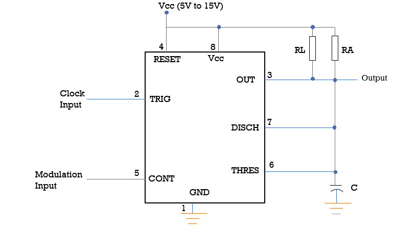
Fig 5: IC 555 PWM using External Modulation
Assign pin two and five as your clock and modulation inputs from the circuit, respectively. And, if you set your course well, you should get output from pin 3.
And for our circuit, we need to provide a clock input or square wave pulse at pin 2. It allows us to set the frequency of the output. Additionally, apply information at pin five whose voltage level or amplitude sets the pulse width dimension.
Therefore, the pulses at pin 2 generate alternating triangular waves at hooks 6/7. Here, the values of C and Ra determine the width of the triangular waveforms.
Applying several pulses at pin two and changing pin five voltage sets the needed PWM pulses at pin 3. The amplitude of the pin five voltage makes the output PWM pulses thinner or thicker.
How to Generate a Fixed 50% Duty Cycle from an IC 555 Circuit
Connect your circuit as shown in the diagram below to produce a fixed 50% duty cycle across the 555 timers.
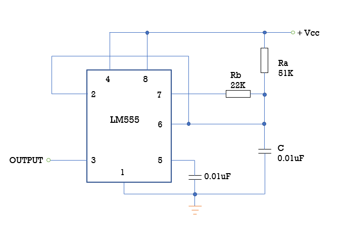
Fig 6: How to Generate a 50% Duty Cycle
You can find the setup in one of the IC 555 datasheets. It provides a 50% duty cycle at pin 3. Additionally, the design is crucial for tasks and processes that require a fast and easy 50% fixed duty cycle.
Conclusion
In conclusion, the IC 555 timer provides a variety of output waveforms determined by the RC network.
Consequently, it has applications in duty cycle oscillators, pulse position modulation, digital logic probes, and DC output voltage regulators.
You can also use it in switched-mode power supplies (SMPS) to control the voltage output to exact values.
Contact us if you have any comments, questions, or additions. We’re looking forward to hearing from you.


