
Several homes and industry appliances depend on semiconductor integrated circuits. They use an H-bridge to drive loads from low power input to produce amplified currents. We have an excellent example in the half-bridge driver IR2104.
But, how exactly does this gate driver work? As you read, you discover all the features and operating conditions. Also, we explain how to use the IR2104 IC in DIY electronic projects.
Contents
1. What is IR2104?
The IR2104 IC is a half-bridge driver. It accepts low-power input to output high-current drives. It feeds the gate of a high-power transistor like a power MOSFET. In addition, the IR2104 gate driver functions as a level shifter and a power amplifier.
The IGBT and MOSFET driver’s output channels run on high and low side references. The logic input runs on 3.3V logic and is compatible with LSTTL and CMOS output. These technologies are immune to proprietary HVC and latch. Therefore, it allows monolithic construction.
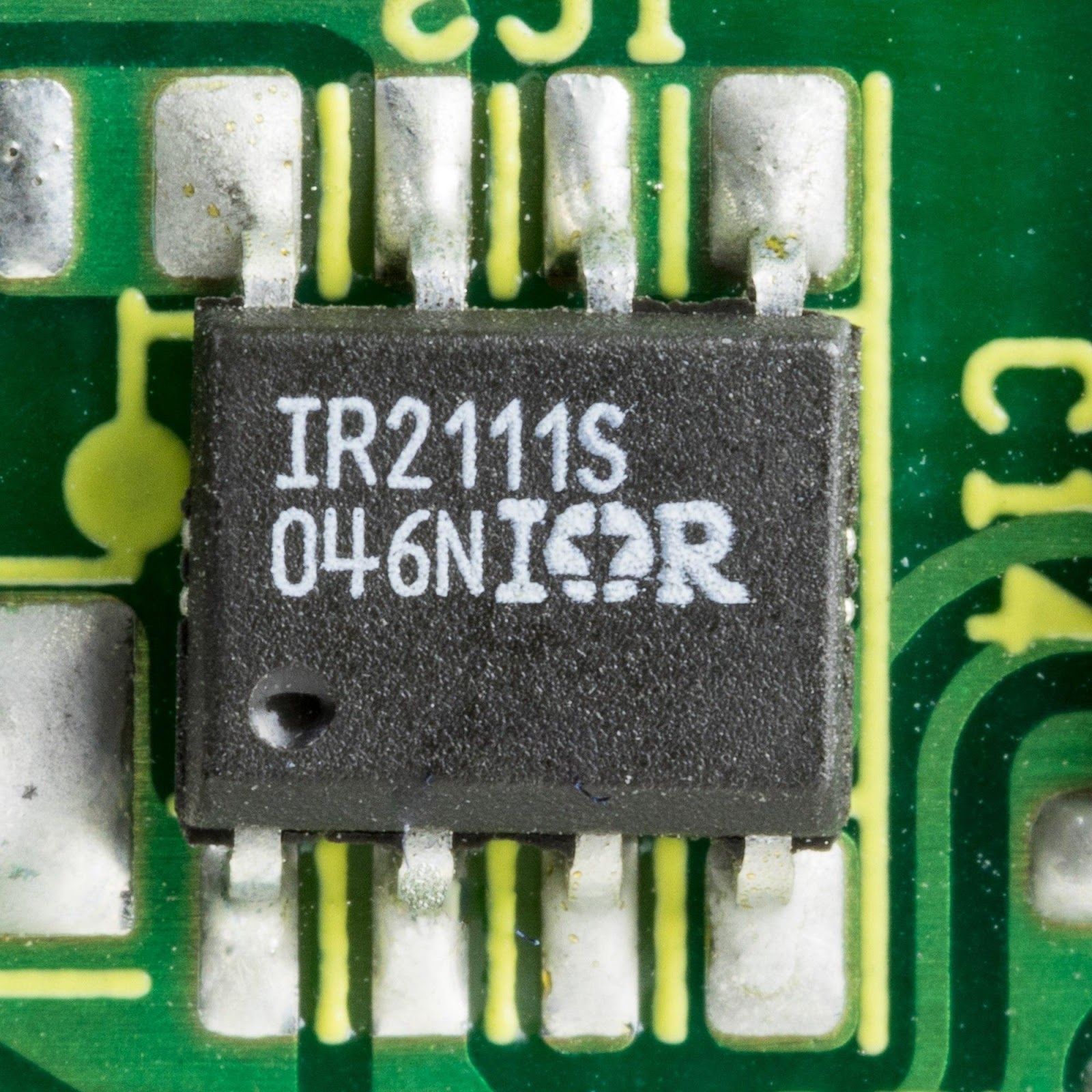
(A similar SOIC package of the IR2014 half-bridge driver).
2. FEATURES
Among others, the IR2104 MOSFET driver has a few outstanding features, such as
- The average load current is 10amps. However, the peak current is 20amps.
- The VCC voltage range is between 12V and 36V DC.
- On the other end, the logic gate voltage supply is 12-15V DC.
- The content of compatible input signals is 3.3V-15V.
- The IR2104 pinout has an SMD-based design.
- It has a single PWM input.
- Also, the IC has a shutdown input feature.
- There are screw terminals for the load supply and load.
- Also, there is an input and logic supply head connector.
- It has a logic that prevents cross-conduction.
3. IR2104 pinout
Typically, the IR2104 pinout features eight mountable pins through a hole. Often, its 8-DIP package comes with two internal drivers of CMOS technology. These, in turn, operate on an N-channel MOSFET and IGBT half-bridge gate configuration.
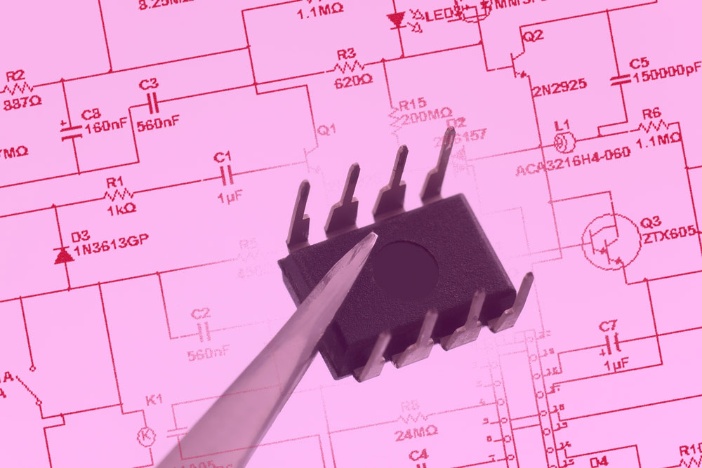
(An 8-pin PDIP driver IC).

4. How to use IR2104
During operation, the half-bridge gate driver uses PWM signals from a controller. An example of such a controller is Arduino Uno. When connected to Arduino via pin D9, it drives the low and high sides of the MOSFET. On the other hand, connecting to Gate pin D8 from pin three on Arduino helps shutdown control signals. The PWM must eventually clock the maximum duty cycle for the charge pump to work.
(A video tutorial on how to use the IR2104 power inverter).
5. Recommended Operating Conditions
These are the necessary limits to observe when using the driver IC to avoid damage. These include:
- TA, Ambient temperature: -40 to 125°C.
- VS, the VCC supply voltage for low side and logic: 10 to 20V.
- Meanwhile, VB, high side absolute voltage: VS + 10 to VS + 20.
- The high side of floating output voltage: VS to VB.
- Also, high side floating offset voltage: Note 1 to 600V.
- The logic input voltage range: is 0 to VCC.
- Also, the output voltage for the low side: is 0 to VCC.
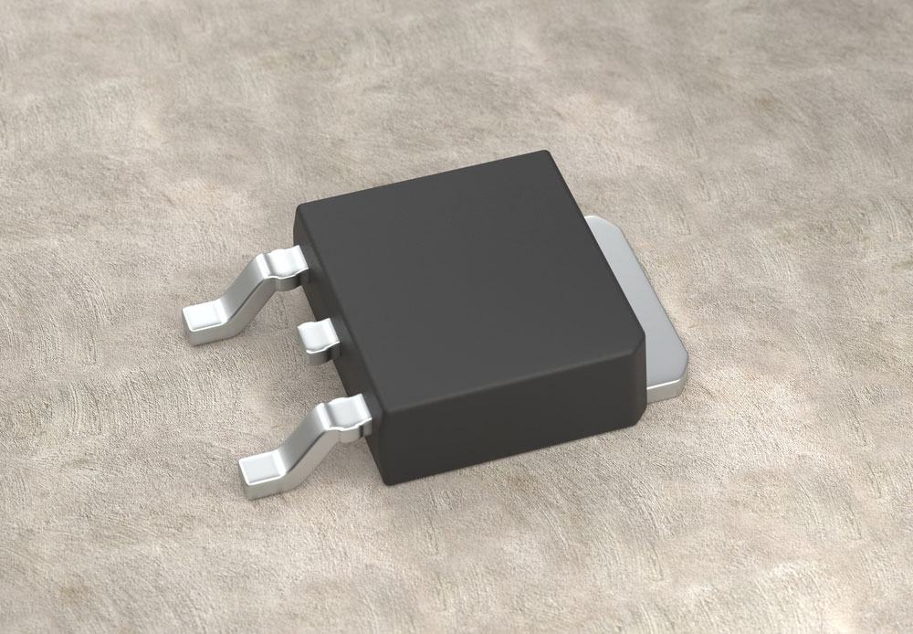
(A typical MOSFET electronic transistor).
Conclusion
Due to an amplifier and level shifter in the IR2104, the IC uses low power input from a microcontroller to produce high current drives. Because of this feature is found in numerous circuit systems such as DC brushed motors, industrial drivers, induction coil drivers, etc.
Nevertheless, using a gate driver like the IR2104 is not only for industry experts but for DIY projects as well. However, building DIY circuits requires the proper professional assistance. Contact us today.


