About Types of Chopper, Most power electronics applications either have complete off or a complete on switching elements. Due to that, their losses are often low, making the circuit highly efficient. However, the current you supply to the load may be discontinuous. It will then require you to provide a high switching frequency or smoothing for better results. In that case, you’ll use a chopper to stabilize the circuit system.
For today’s article, we will discuss the classification of choppers based on several features such as the commutation process, and more.
Contents
- 1 1. What is a Chopper Circuit?
- 2 2. How Does the Chopper Work?
- 3 3. Types of Chopper
- 3.1 Based on their operation principle
- 3.2 Based on the commutation process
- 3.3 Based on power loss occurring at switching time choppers
- 3.4 Based on output voltage values
- 3.5 Classification based on Quadrant Operation
- 3.6 Class-A chopper/ Type A chopper
- 3.7 Class-B chopper/ Type B chopper
- 3.8 Class-C chopper/ Two Quadrant Class-A chopper/ Type C chopper
- 3.9 Class-D chopper/ Two Quadrant Class-B chopper/ Type D chopper
- 3.10 Class-E chopper/ Type E chopper
- 4 Applications of Chopper
- 5 Conclusion
1. What is a Chopper Circuit?
A chopper (or DC equivalent of an AC transformer) is a semiconductor electrical device. It functions to change a fixed DC input voltage (Vs )into a variable DC power or output voltage/ Vo. The DC output value may be less than the source voltage or more than the input voltage.
2. How Does the Chopper Work?
Generally, a chopper circuit has a load, resistor, and a semiconductor diode, as per the diagram below.
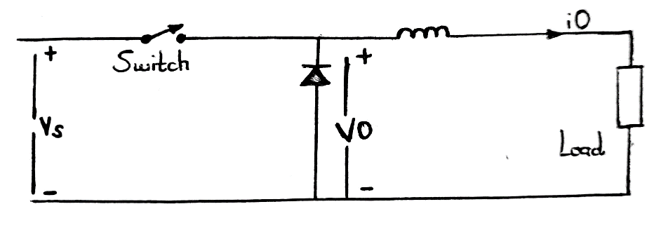
A circuit diagram of a chopper
It operates at high-speed to connect the source to the load, then disconnects the load from the basis. Using the diagram, we can conclude the working principle as;
- Switch SW is the chopper, and at high speeds, it can be an ON or OFF switch. For that reason, you can disconnect or connect the load from Vs (a supply source). Also, the periodic opening and closing of the circuit eventually control the output voltage.
- ON-switch results in source voltage being equal to the load voltage. Conversely, when it’s an OFF-switch, the load voltage equates to zero.

3. Types of Chopper
We have classified choppers based on their features as follows;
Based on their operation principle
The operation principle is the best way in which you can classify a chopper. The two types include;
AC link chopper
Here, there’s a voltage inversion whereby an inverter converts a DC voltage into an AC voltage. Next, you pass the AC through a step-up or step-down transformer. Finally, a rectifier converts the transformer’s output into DC.
DC chopper
DC choppers act as step down and step transformers on DC voltage. As such, they can change a constantly steady DC voltage to a lower or higher value depending on the type.
Based on the commutation process
Natural commutated chopper
Natural commutated chopper works on AC circuits in that the supply voltage is from an AC source. Because of that, when there’s a negative voltage crossway to the SCR or thyristor, it turns off.
Forced commutated chopper
A forced commutated chopper operates on DC circuits. You can achieve the commutation by lowering SCR current below the current value or reverse biasing the SCR component. Examples are Morgan chopper and Jones chopper.
Based on power loss occurring at switching time choppers
Hard switching chopper
Hard-switched chopper circuits use their ability to operate.
Soft switching chopper
Soft switching choppers use LC resonant circuits to turn off or turn on the device at zero voltage or current.
Based on output voltage values
The classification of chopper circuits here has a basis on the output voltages.
Step-up or Boost chopper
The chopper has a lower source voltage than the average DC output voltage (Vo ˃Vs) for the first one. Also, there’s a flow of power from the load to the source. Here, the load current has an emf source and is inductive.
Step-down chopper
The source voltage is higher than the average DC output voltage (Vs ˃Vo). On the contrary, the power flow is from the source to load.
Classification based on Quadrant Operation
Chopper circuits limit the current flow direction through them since they are semiconductor static devices. However, you can modify how your chopper operates in four quadrants, then yield five types of chopper.
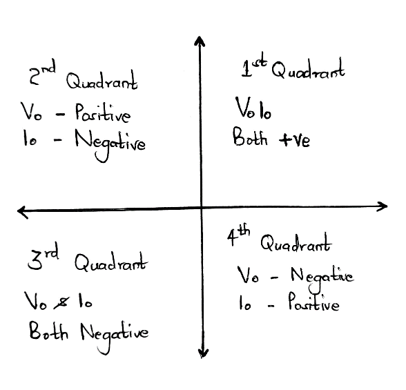
The four chopper Quadrants
Class-A chopper/ Type A chopper
Class-A chopper only works in the first quadrant. Therefore, the load voltage (VO) and load current (iO) will always be positive. Additionally, power transfer is from the source to the load, an example being a step-down chopper.
Class-B chopper/ Type B chopper
It operates in the second quadrant. Thus the load current is negative while the output voltage of the chopper is positive. Here, the negative load current (io) power transfer is from the load to the source. A step-up chopper circuit is an example.
Class-C chopper/ Two Quadrant Class-A chopper/ Type C chopper
Parallelly connecting class-B and class-A choppers gives a class-C chopper that operates in the second or first quadrant. So, it’ll act as a step-down chopper in the first quadrant and a step-up chopper in the second quadrant.
Class-D chopper/ Two Quadrant Class-B chopper/ Type D chopper
It operates in both the fourth and first quadrant and can transfer power from load to source or source to load. Then, you can reverse the average DC output voltage with a class-D chopper, whereas the load current direction isn’t reversible.
Class-E chopper/ Type E chopper
Lastly, we have a class-E chopper that works in all quadrants as it is a universal chopper. In addition, you’ll need four diodes and four choppers/four semiconductor switches to make a class-E chopper circuit. You’ll need an inductive load for the chopper to function. Additionally, there should be a reversed polarity of load emf in the fourth and third quadrants.
Applications of Chopper
You can use the chopper circuit in a range of applications comprising:
- Battery charges,
- DC voltage boosting,
- Switched capacitor filters,
- Lighting and lamp controls,
- In driving brushless torque/stepper motors in actuators,
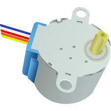
Stepper motor
Source:https://www.google.com/imgres?imgurl
- Variable frequency drives,
- Signal processing systems,
- Airplanes and spaceships,
- Speed controllers in DC motors,
- Railway traction systems,
- Solar energy conversion,
- Electric cars with battery operation,
- Switched-mode power supply systems such as DC to DC converters
- Finally, Class D electronic amplifiers.
Conclusion
To sum it up, several technological industries are adopting choppers for rapid transit systems. Moreover, chopper circuits have high efficiency, quick response, regeneration abilities, and smooth control. Other times, you can use some power semiconductor devices in a chopper, e.g., IGBT full form and a force-commutative thyristor.
That’s it for today, and we hope that you’ve gained as much on choppers. In case of any clarifications or inquiries, reach out to us, and we’ll work it out together.


