A stepper motor is a motor type that works by converting electrical energy to mechanical energy. The A4988 pinout is an example of this stepper motor. It’s a trendy micro-stepper motor since it is very affordable and durable.
In this article, we will discuss the a4988 stepper motor, its features, pinout description, and the step-by-step process of connecting one.
Contents
What is an A4988 Stepper Motor Driver Module?
An a4988 is a micro-stepping driver with a built-in translator that helps make the operation easier. The design of the motor is to operate a bipolar stepper motor in step modes. When you input a single impulse on the STEP input, it drives the motor in one micro-step. Also, the motor structure consists of a fixed current regulator. This current regulator has the potential to work in slow or mixed decay modes.
Moreover, with an a4988, there’s a lack of a phase sequence, complex interfaces to the program, and high-frequency control lines.
Additionally, the motor interface type that an a4988 motor provides is ideal for projects where microprocessors are unavailable or overburdened.
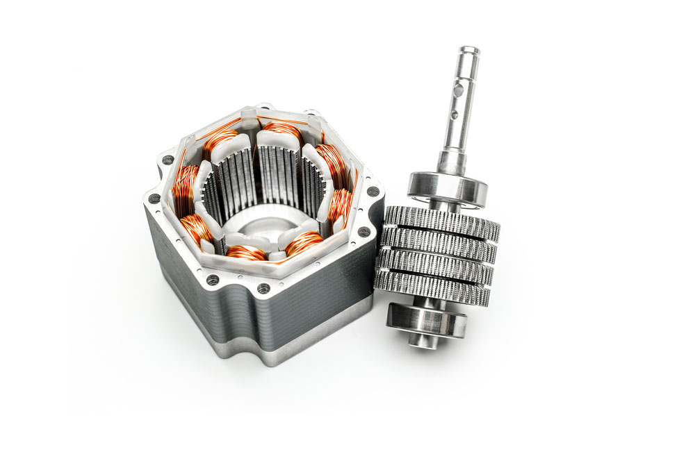
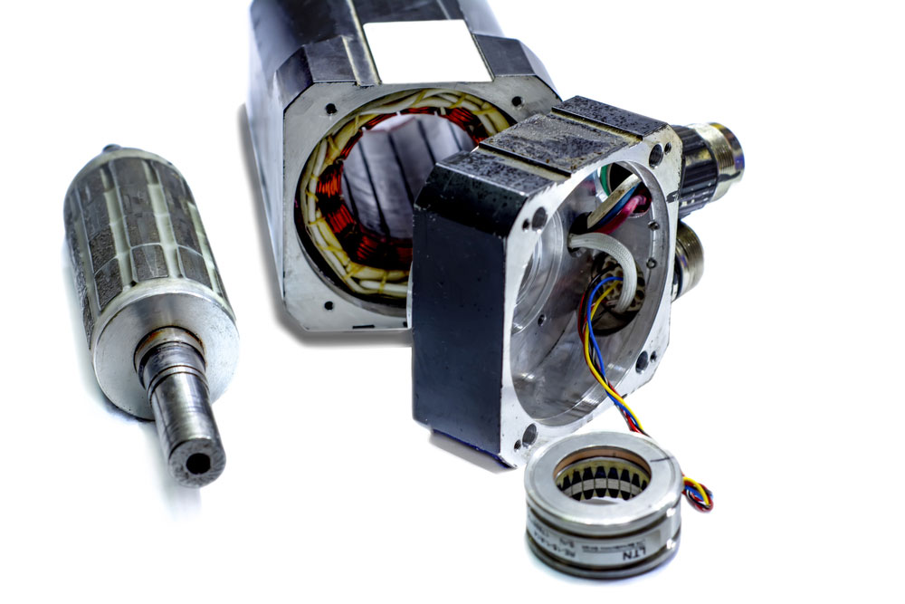
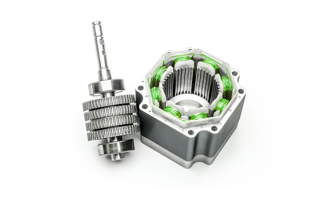
(a disassembled stepper motor)
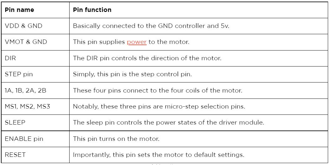
A4988 Pinout Configuration
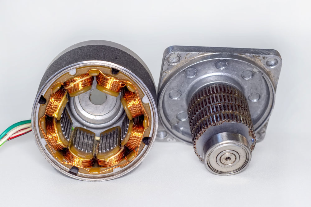
(a disassembled motor with rotor set side.)
A4988 Features and Benefits
- First, the a4988 electronic equipment has five selectable modes. For example, these are the full, ½ step, ¼ step, 1/8, and 1/16 step.
- Secondly, the device possesses short-to-ground and short-load protection features, with the motor having a thermal shut-down circuitry.
- Thirdly, the device has no reverse voltage protection but has crossover current protection and relatively low RDS(ON) outputs.
- Moreover, it has an automated current decay mode detection and a 15.5mm by 20.5mm.
- Additionally, the stepper motor has a maximum operating voltage of 35v and a minimum operating voltage of 8v.
- Further, the A4988 hybrid stepper motor driver has a simultaneous rectification for low power dissipation.
- Lastly, the max current per phase is 2A with an internal UVLO.

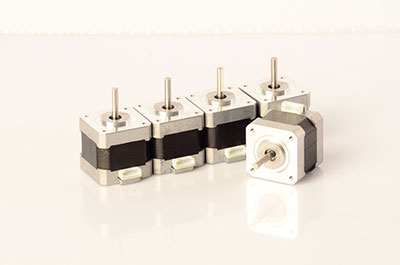
(an electric stepper motor.)

A4988 Alternative Products
Similar to any other electrical equipment, the a4988 motor has alternative options. Notably, its alternatives include the DRV8825, L6207, L6474, L6208, TMC2209, and TMC2208.
How to use the A4988 Driver Module?

(Diagram of an a4988 electronic circuit with a microcontroller.)
A project example is wiring an A4988 driver module & Arduino. The motor connections of an A4988 driver & Arduino are very simple.
Connection steps.
The initial connection connects the VDD and GND pins to the 5V and GND pins on the Arduino.
Next, connect the direction pin and STEP pin to the #2 and #3 output digital pins on the Arduino. Also, ensure you connect the 1B, 1A,2B, and 2A pins to the stepper motor. Note, it’s very convenient to use an a4988 stepper since its layout matches a 4-pin connector found on many bipolar motors.
Now, enable the driver by joining the RST pin to the SLP pin. Keep in mind that to operate the motor in full-step mode, always leave the micro-step selection pins disconnected.
Lastly, connect the VMOT and GND pins to the motor power supply. Always ensure to use a decoupling electrolytic capacitor even though a low-ESR ceramic capacitor is present in the driver. The decoupling capacitor protects the driver from voltage spikes.
Notable Tip:
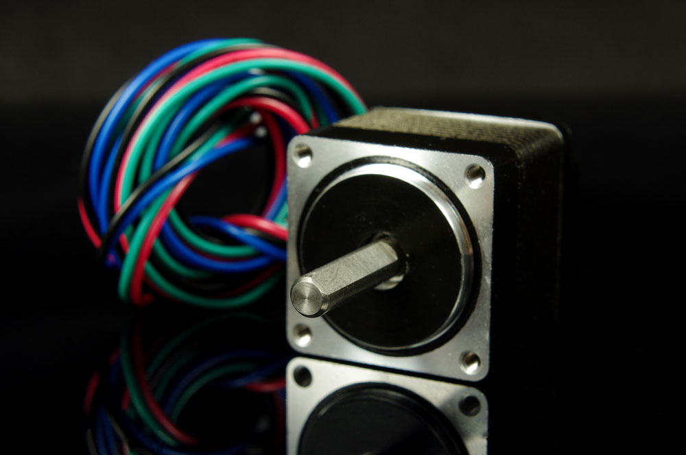
(an isolated stepper motor with wires.)
A4988 Pinout: Code
Below is a simple Stepper Motor Control Example Code

(Image of the stepper motor control code )
Copy and paste the code above to your IDE.
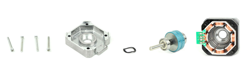
(a deconstructed stepper motor).
Set the DIR pin to a high or a low to achieve a successful connection. Notably, the motor will rotate clockwise when set to high. However, when low, the motor will shift in an anticlockwise direction.
The STEP pin receives a frequency of pulses that determines the stepper motor speed. A pulse, in this case, is the process of pulling the output HIGH. Then, waiting for a while before pulling the same output LOW, and again waiting. Any change in the waiting period between the two pulses changes the pulse frequency, changing the motor speed.
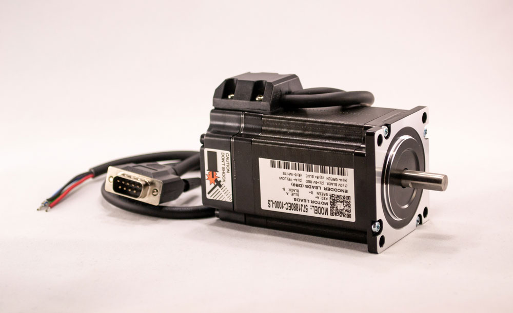
(an electric motor.)
A4988 Pinout: Current limiting
Before using the motor, you need to adjust and limit the current flowing through the motor coils. 2A is the maximum current that can flow through the coils. Therefore, to set the current limit, use the current limit potentiometer on the a4988 driver. Also, set the current limit at a lower or equal rating to the motor’s current rating.
- First, check the datasheet for the current ratings to make adjustments.
- Second, leave the driver in a full-step mode.
- Third, do not cloak the STEP input. Significantly, this will help to hold the motor in a fixed position.
- Next, use the trimmer potentiometer to measure the reference voltage(Vref) when you make the adjustments.
- Finally, use the current limit = Vref x 2.5 to adjust the reference voltage.
(a picture shows different types of motors.)
A4988 Application
- children’s toys applications.
- robots use an a4988 hybrid stepper motor to control their movements.
(a stepper motor interface type with a green wire.)
Summary
This article gives you information on what the AD9850 DDS signal generator module does, its connections, and how they work. If you’re interested in learning more about your module-related projects, contact us! Our team is always happy to answer any questions from you!