Contents
1. What is the AGC Circuit?
Automatic Gain Control is a system for regulating amplitude in the electronic circuit in an amplifier by ensuring the output signal is at a constant level.
Despite the amplitude variation of the incoming signals, it adjusts the average output signal, which changes the amplifier’s gain.
The system works in a feedback loop, meaning the output signal finds its way back as an input signal. The circuit can redirect the call back into the system through a cause-and-effect chain, resulting in a loop cycle.
The system can also facilitate corrections and adjust to changes, hence the Closed-loop AGC System.

Blockchain diagram of the AGC circuit
2. What is the Function of AGC?
AGC is a standard method of gain recovery in seismic processing. When studying marine seismic waves, scientists apply AGC systems to the data. The application of AGC on the data makes it more visible since scientists can not perceive some information without it. The information that is lost is due to amplitude decay.
It is ideal because amplification effects are automatic on electrical signal amplitude.
The application is based on a trace by trace using an AGC operator length. Hence the procedure helps calculate amplitudes through a scale factor in the AGC operator length.
Notably, the AGC operator length, also known as the AGC window, is essential for AGC gain correction and generally has a millisecond duration.
The AGC window is a duration of milliseconds that scientists use on the seismic data sample at different time constants.
It is the ideal choice of processing tool as it is easy to apply and utilize for those familiar with the concept. However, it has the shortfall of erasing amplitude information within the seismic data.
3. Basic Working Principle of AGC
The simple principle of the AGC system is to have automatic control of the signal output. It does this by changing the variable input amplitude of a radio receiver to have output amplitude equalization.
Automatic Gain Control circuit systems also conduct amplitude modulation to solid signals.
The DC bias voltage from the emitter controls the gain from the amplifiers just like it happens in tube circuits. The AGC system eliminates the need to readjust again when there is fluctuating signal strength.
It is important to note that gain is the ratio of the constant output amplitude to the input signal level in an amplifier circuit.
Bipolar transistor receivers with the AGC system function by requiring power because of the gain signal sent back.
If there is enough AGC power variation, the base current can easily control the emitter current.

4. The AGC circuit
This section will work on a project that requires an AGC circuit. Our goal is to amplify microphone audio signals.
The demonstration will show the working of a maximum frequency gain audio amplifier, not forgetting amplifier circuitry.
We will look at components individually and then see how they relate in a circuit.
i. Microphone connector
The microphone connector has a circuit that makes it an active device for transmitting weak audio signals.
A diaphragm vibrates because of the weak signal and communicates through the course as a current. The sound waves go into the mic as a weak input signal of varying wavelengths.
The current flows through a resistor in DC voltage in our microphone circuit. A coupling capacitor separates the varying input signal in subsequent courses.
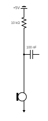
Circuit diagram of the microphone connector
ii. voltage amplifier
In this stage, the amplifier, with a single transistor, boosts a weak audio signal from the microphone. The circuit has maximum gain to amplify the audio signal efficiently.
The transition connection acts as an input and output terminal, with the emitter terminal for both.
As the resistor-capacitor value rises with the gain in the circuit, ensure there are no incoming signals. The purpose is to provide the amplifier stays dormant. However, in this instance, the circuit is a transistor circuit, ensuring that the output voltage is half the total voltage in the course while idle.

A circuit diagram of the amplifier
iii. AGC + Amp
We will utilize a negative feedback amplifier with additional feedback on the positive pin. Therefore, the gain will also depend on the circuit connection on the positive pin.
.
On the positive side, the Field Effect Transistor can function as either a variable voltage resistor or as a transistor.
The capacitor (C1) signals from the operational amplifier to the transistor base in a circuit with all the components. Consequently, R2 and C2 help convert the AC energy to DC.
Working mechanisms of C2, R4, and Q1 are closely similar to a single-phase diode. The output voltage is directly proportional to the output of the amplifier.
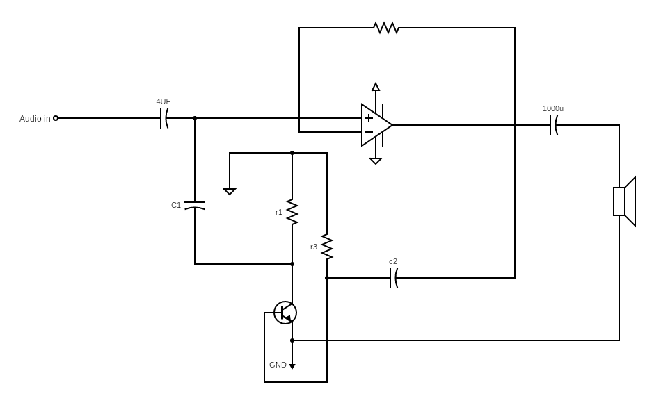
Circuit diagram of the amplifier with audio input and output
Supply Voltage at the FED gate facilitates mutual conductance, acting as a voltage variable resistor. In that spirit, if the gate voltage increases, it results in more conduction, thus lowering the receiver gain. If the gate voltage drops, it reduces conduction from the ground to the positive pin, increasing the amplifier’s gain. In that spirit, if the gate voltage increases, it results in more conduction, thus lowering the receiver gain.
If voltage is ignorable, there will be no conduction on the positive pin. The outcome will be the circuit acting as a negative feedback amplifier.
In such a state, we can use the formula G = – (R2 / R1) dB for amplitude measurement to ascertain that gain is at maximum.
Watch this video to understand further and see a demonstration of the system at work.
5. Applications of the AGC
The most extensive use of the AGC is in AM receivers. It is helpful in many modern radio receivers to regulate audio signals. There would be a linear amplifier system without the system where audio signals would fluctuate with signal strength.
FM receivers also use the AGC system to prevent overload by more robust signals.
The system is helpful in radar systems as it helps reduce noise contribution by reducing unwanted echoes.
The system helps reduce the signal-to-noise ratio when recording audio. There is more prominent noise when the audio device’s input signal level is low.
In such instances, the AGC can be an alternative to high-fidelity recording as it reduces the gain as the signal increases.
AGC effects also apply to telephone recordings. The system helps record both parts of a conversation for optimum performance of the call recording feature.
The system is also essential in Voice-operated gain-adjusting devices (Vogad). It is a type of microphone amplification that reduces the dynamic range.
Vogad is also in radio transmission systems as it takes a wide variety of signals and transmits the signs at an acceptable range.
In biology, AGC is more prominent in the sensory field. An example is the visual system of vertebrates that uses calcium regulation to sight light levels.
It would be best to keep in mind that climatic conditions impact signal conditions in the AGC system.
Conclusion
We have extensively seen how signal strength regulation happens within the AGC system. So you now understand what goes on in the different amplifier stages. Should you decide to try and put theory to practice, you now have all the necessary information to test out the system under various signal conditions. for more information regarding the circuit or a source for these components, contact us.


