Contents
Introduction to AM Radio Circuit
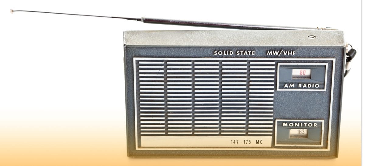
An AM (Amplitude Modulation) transmits data via radio carrier waves, often in electronic communication. Further, it is a modulation strategy where the amplitude of the carrier wave will constantly change depending on the message signal on transmission.
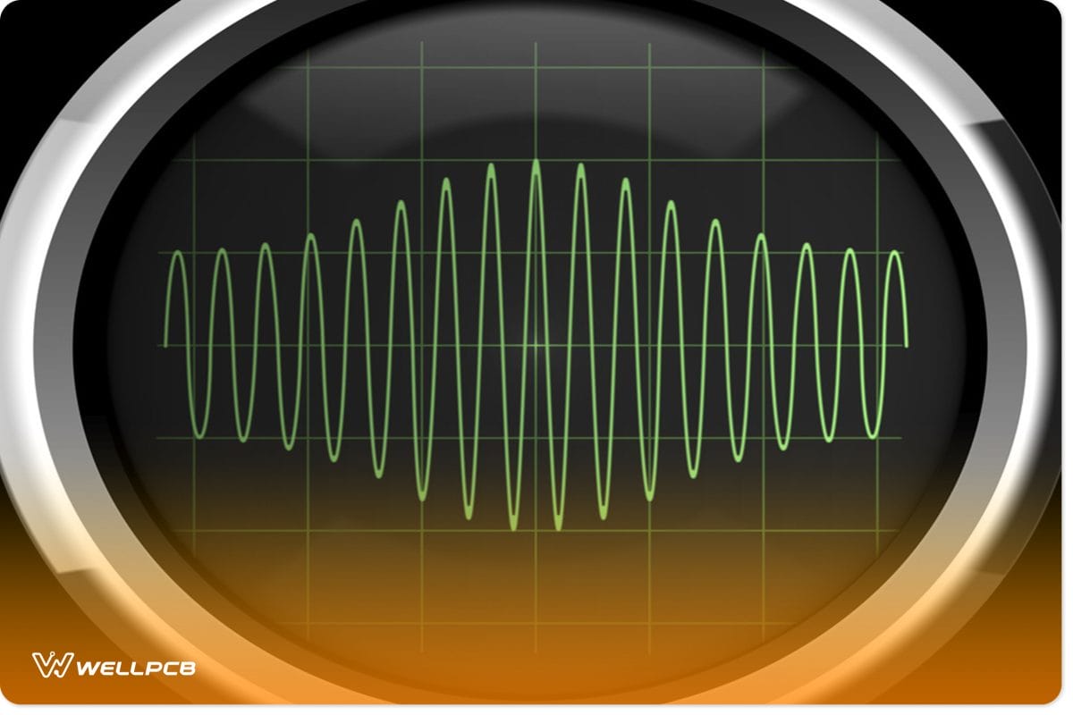
(signal with amplitude modulation).
Mostly, you’ll come across two key stages of an AM receiver. They include an Intermediate Frequency (IF) and Radio Frequency (RF). Additionally, there’s an RF-to-IF converter or mixer, an audio speaker, and a demodulator.
An RF-to-IF receiver uses an oscillator with a variable frequency (contrary to the RF carrier frequency). In other words, the demodulator will majorly work with a radio signal if you convert the carrier frequency of a radio signal to IF.
Thus, if you tune to a channel, you will simultaneously tune a close-by oscillator and RF tunable channel if you tune to a track. Also, note that for adequate selectivity, all stations have to adhere to a fixed carrier frequency. The earth wire or external antenna may, however, be of minimal use in radio stations.
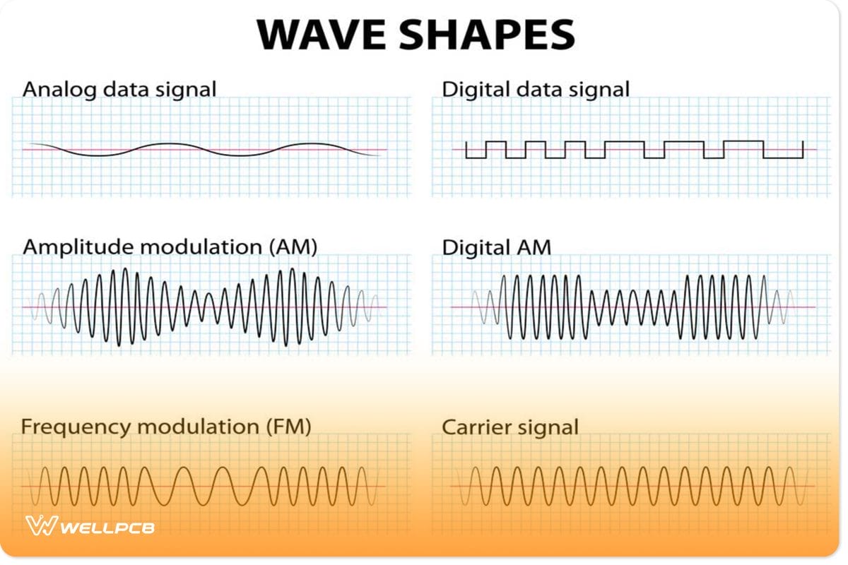
(wave shapes of an AM radio)
Making an AM Radio
Single transistor AM receiver circuit
First, let us start by making an AM radio that uses a single transistor.
- Materials that you need to prepare
| Serial Number | Components | Value | Quantity |
| 1 | Headphones | N/A | 1 |
| 2 | Resistor | 22Ω, 820K | 1, 1 |
| 3 | Transistor | BC547 | 1 |
| 4 | Coil | 80 turns | 1 |
| 5 | Diode | 0A91 | 1 |
| 6 | Long antenna wire | N/A | 1 |
| 7 | Capacitor | 100nF, 10nF | 2, 1 |
| 8 | Variable capacitor | 365pF | 1 |

- How to operate the circuit
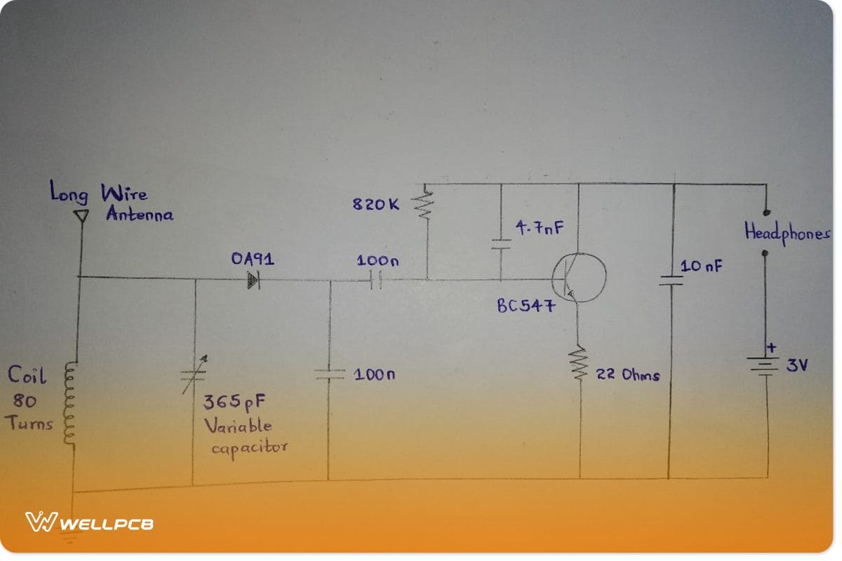
The single transistor AM radio circuit works as follows;
- There’s a 365pF variable capacitor and coil that consists of the main AC circuit. They, therefore, receive signals through the receiving wire, which is a nice wire antenna in our case.
- Next, the OA91 diode identifies the signal.
- Then, the BC547 transistor amplifies it.
Finally, the resultant radio output gets to the headphones. It is where you use the course for testing. However, if it doesn’t work, consider checking for defects in the circuit above.
2- Transistor Radio AM Circuit
- Materials that you need to prepare
| S. No | Components | Value | Qty |
| 1 | Capacitor C1 | 500pF | 1 |
| 2 | C2 | 0.1uF | 1 |
| 3 | C3, capacitor C4 (non-polarized capacitor) | 470pF, 47uF | 1 |
| 4 | T1 | 2SC3112 | 1 |
| 5 | T2 | 2SC3122 | 1 |
| 6 | Speaker – from a small earphone | 10k | 1 |
| 7 | L1 – an ordinary antenna coil | 1 | |
| 8 | R1 | 1K | 1 |
| 9 | R2 | 1M | 1 |
| 10 | R3 | 39K | 1 |
| 11 | R4 | 6.8K | 1 |
| 12 | R5 | 2.2K | 1 |
| 13 | TRIM | – | 1 |
Circuit diagram
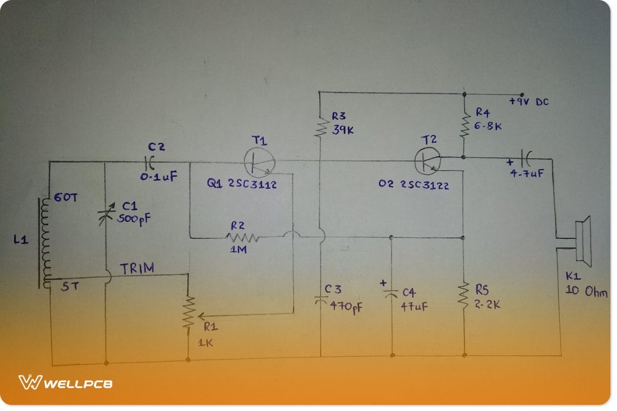
Explaining the 2-transistor basic circuit functioning;
- First, the tank circuit consists of capacitor C1 and coil L1.
- Secondly, the transistor Q1/T1 is a demodulator – the demodulated signal is at Q1’s base.
- In addition, further amplification is achievable when the base of Q2 is in combination with the audio signal. Then, the system avails an amplified audio signal at Q2’s collector.
How to operate the circuit
- First and foremost, the antenna coil will collect MW signals from the surrounding air.
- Then, before proceeding to the next stage, the trimmer will first set and then tune the frequency.
- In the third stage, T1 acts as both the demodulator and high-frequency amplifier. T1 extracts audio from the signal it receives and then takes it through an amplification process before passing it to the last stage.
- Finally, T2, which is an audio amplifier, further amplifies the demodulated signal at its base. Often, the signal amplification here is audible enough on the connected speaker, loud and clear. But, to avoid a bad speaker, ensure it is 10 ohms.
FAQs about AM Radio Schematic
- How will I capture the Unwanted AM Radio Signals?
So, there may be cases where the unwanted transmitted signals, other than the usual AM signal, find a way into the
First of all, you may need an old radio to get some necessary components. For instance, you’ll need an inductor L1 to act as a broadcast loopstick-antenna coil and a capacitor C1 to tune in the radio. Then, you can control the tunable AM signal trap circuit to get the unwanted AM signals, after which the remainder signals get channeled to the receiver.
Briefly, here’s how you should arrange the circuit.
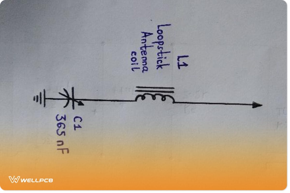
So, there may be cases where the unwanted transmitted signals, other than the usual AM signal, find a way into the tank circuit. Under such a circumstance, ensure you examine the transmitter’s frequency, then choose a suitable capacitor arrangement that matches the frequency. Afterward, use the schematics above to connect your new combination.
How do I make AM Radio Schematic Audio Amplifiers?
Let us consider the above diagram of an audio amplifier’s circuit.
- First, the push-pull amplifier consists of transistors TR4, TR3, and TR2, whereby TR2 acts as a driver stage, whereas TR4 and TR3 assimilate complementary output pairs.
- Often, TR2 amplifies the pure audio signal from TR1.
- Then, amplified negative cycles get fed into TR3, while TR4 receives the amplified positive cycles via a D2.
- After completion of the amplification process, C7 combines the two audio signals that eventually produce the output audio on the LS1 (loudspeaker).
In terms of functioning:
- T1 operates as both the detector that has a +ve feedback and the radio frequency amplifier. Thus, you can easily manipulate the MW receiver’s sensitivity and feedback level by varying P1.
- The uppermost section of the circuit C1/L1 produces the output to T1’s base even though T1’s impedance can fully ensure almost no suppression to the resonant circuit.
- In addition, T1’s collector detects the signal, while C3 and T1’s output impedance thoroughly examines the radio frequency portion of the signal.
T2 further amplifies the a.f. Signals, and in turn, the signs run the crystal earpiece attached to the project.
(old analog integrated circuits in an analog radio)
Conclusion
To sum it up, now that we have shown you a couple of ways you can make an AM radio signal, how about you try out the project? Also, we do hope the Frequently Asked Questions have helped you. However, we are still open to more questions and clarification. Kindly reach out to us, and we’ll get back to you with solid answers.


