
Contents
ams1117 Pinout Configuration
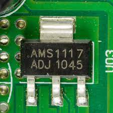
AMS1117 Pinout
From left to right: Ground, Output, and Input pins
An AMS1117 has three hooks in its pinout configuration, as we’ll discuss below.
- Input voltage (Vin)
The first pin, Vin, receives the input voltage, which later undergoes regulation and production at the output voltage.
- Ground/ Adjust pin
Generally, the pin adjusts or configures the output voltage; however, it’ll function as a ground pin if you have a fixed voltage regulator.
- Output voltage (Vout)
Lastly, the Vout pin produces the regulated output voltage, which the adjusted pin has configured.
Features of the AMS1117
The features or characteristics of ams1117 include the following;
- First of all, ams1117 is a low drop-out (LDO) voltage regulator.
- Additionally, it can act as a 3-terminal adjustable/fixed linear voltage regulator.
- Then, it has an inbuilt current limiting and thermal protection.
- Also, it’s available in three packages: TO-252 package, SO-8, and SOT-223 packages.
- The maximum output current is 1000mA/1A.
- Load regulation: 0.4% maximum.
- Line regulation: 0.2% maximum.
- The range of adjustable/variable voltage is 1.25V to 13.8V.
- The maximum drop-out voltage is 1.3V.
- The maximum input voltage is 15V.
- Ranges in fixed voltage type include 5V, 3.3V, 2.85V, 2.5V, 1.8V, and 1.5V.
- The operating junction temperature is 125°C.
AMS1117 application
Applications of ams1117 include in;
- Battery chargers,
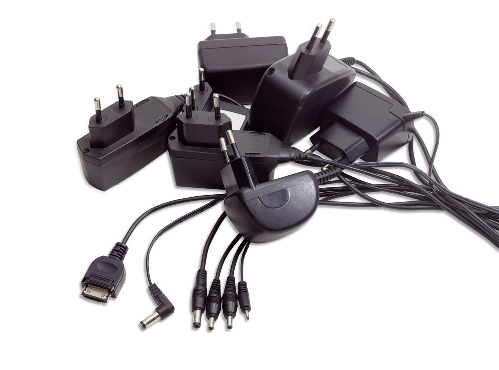
(battery chargers)
- Battery-powered instrumentation,
- Current limiting circuits,
- High-efficiency linear regulators,
- Motor control circuits,
- Power management for notebook,
- Reverse polarity circuits,
- 5V to 3.3V linear regulator,
- Active SCSI terminators,
- Post regulators for switching supplies.
Where to Use AMS1117?
As you’ll see, there are several types of ams1117, depending on their output voltage and package type. However, all of them have a maximum current of 1A.
They’re popularly applicable in Arduino boards, which regulate 3.3V and 5V of power supply.
Also, you can use the ams1117 stabilizer in similar circuits as an LM317. Ensure you check the output current and maximum voltage of the stabilizer.

AMS1117 Substitutes
An ams1117 has a couple of substitutes that may come in handy when you lack or misplace the IC. For example, there are K1254EN, IL1117A, and LD1117A.
Furthermore, you’ve probably heard of LM1117. It’s similar to ams1117 but differs in some features like its SOT-223 version having 800mA maximum current.
Moreover, you can substitute the voltage regulators with NTE9060, LM317, or LM7805.
How to use AMS1117?
In terms of the application circuits of ams1117, we’ll consider two courses and voltage regulators.
The adjustable voltage regulator circuit
- For the first voltage regulator circuit, we’ll need two external resistors. Functionally, the resistors decide the regulator’s output voltage.
- Further, we have a capacitor Cadj (optional component), whose application improves ripple rejection when necessary.
- Finally, our two remaining capacitors respectively filter the input and output noise.
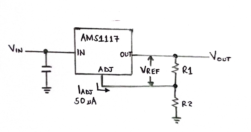
Circuit of an adjustable voltage regulator using ams1117
The fixed voltage regulator circuit
Our second ams1117 application is in a fixed voltage regulator.
Using it here is very easy.
- Start by powering ams1117 through the input voltage pin. Then, obtain your regulated output voltage from the output voltage pin.
- In our fixed regulator case, we’ll use a ground pin instead of an adjusted pin, meaning the voltage will remain grounded.
- In addition, you can use a capacitor at the output side to help in noise filtration.
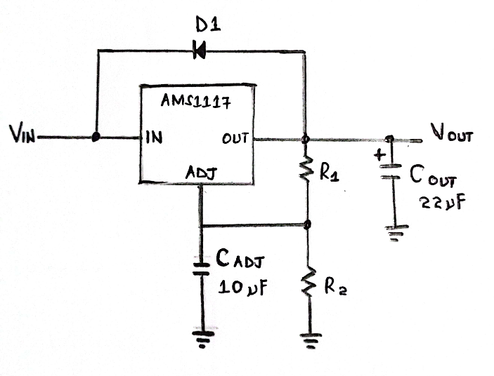
Circuit diagram of a fixed voltage regulator
Note;
- We don’t use protection diodes between the output pin and adjustment pin in both application circuits to prevent circuit overstressing. Instead, we use the internal resistors that limit current pathways on the ground pin.
- Then, you won’t need any diodes between the output and input.
So now that we’ve learned how to apply the IC ams1117 regulator, let us calculate its output voltage.
But first, select the values of R2 and R1 (less than 1K) depending on the project’s output voltage. If you want to vary your output voltage in real-time, use a variable resistor as R2.
The formula is;
VOUT = VREF (1 + R2/R1) + IADJR2
AMS1117 encapsulation
AMS1117 can exist in the following encapsulations;
- Eight lead SOIC plastic packages,
- Three lead SOT-223 plastic packages, and
- TO-252 (DPAK) plastic package.
Conclusion
That’s a wrap for today. Besides being favorable for devices, it can also serve different voltage regulators. If you need an SMD component regulator, then ams1117 IC is a perfect choice. If, however, you have questions, kindly contact us, and we’ll help you to the best of our abilities.


