An Arduino proximity sensor is a handy, inexpensive gadget that detects the presence of an object within its sensing range. This could be anything from a human to a pet or even something as small as a bug! It’s really easy to make one yourself.
Have you ever wanted to know how Arduino proximity sensors work?
It uses IR (infrared) waves to detect nearby objects within its sensing distance. This article will go over everything about Arduino proximity sensors. Let’s start!

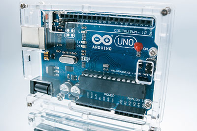
(Arduino Uno Breadboard)
Contents
What is an Arduino Proximity Sensor?
An Arduino proximity sensor is a device that senses the presence of an object in its vicinity. It consists of an infrared proximity sensor connected to an Arduino Uno circuit and a breadboard.
It works by pulsing an LED on and off at a constant rate (frequency). By this, it measures the time taken by reflected light pulses from surrounding objects returning to it after hitting them.
(Proximity sensors icon)
Hardware Components Needed for Arduino Proximity Sensor
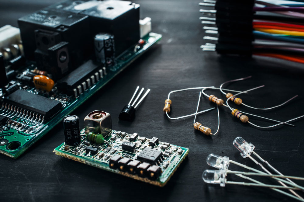
( Electronic components)
The hardware components needed for Arduino proximity sensor setup are:
- A breadboard
- An LED (you can use an RGB led instead of the white one)
- Two resistors, each having a value within the range of 200 – 1000 ohms. (However, when using LEDs other than white ones, you need to have different values for each. This helps to get better results)
- An Arduino Pro Mini board or similar.
- An infrared proximity sensor module (e.g., HC SR04 Ultrasonic sensor Module -distance). This is a critical component in the setup.
- Jumper Wires
NB: Make sure you have a USB cable to connect your Arduino Uno board with the computer for code uploading purposes!

(Electronic assembling tools)
Infrared Proximity Sensor Pinout: Easy Connection Explained
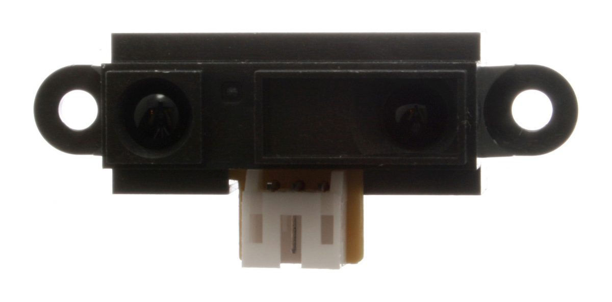
( IR proximity sensor)
In brief, to easily understand the 3-pin connector of the IR sensor, they will come packed with connecting wires. The wire connectors are; black wire (output), blue wire (GND), and finally, the brown wire is VCC.

Steps to Making an Arduino Proximity Sensor

( A technician repairing a computer)
When setting up an Arduino Proximity Sensor, it is essential to understand these Arduino board pins.
VCC (5v)
This is the power supply pin to the Arduino Pro Mini board. Therefore, it needs a voltage range of +5volts. To function properly, you should use a battery pack with at least 11V output. The Arduino’s VCC pin or 5v connects with the brown wire from the IR sensor.
GND
Ground pins get connected with electrical circuits that need to have low resistance paths from one point to another. In this case, it’s meant for mounting all ground circuit connections on your board and the Arduino proximity sensor module. The Arduino’s GND pin connects with the blue wire from the IR sensor.
Echo/AO
The output (echo pin) on the HC-SR04 Distance Sensor Module is responsible for triggering the ultrasonic emission. So, this output pin goes high when a pulse starts transmitting, otherwise, it remains low. Arduino’s proximity sensor’s AO pin connection to the IR sensor is by the black wire.

( Image of miniature figures working on a circuit board)
Step by step connection and working explanation
The following are the steps to make your own Arduino proximity sensor:
- First, you need to upload a complete code on your breadboard. This ensures that all hardware components are working according to their respective declarations.
- Also, ensure that at least one LED has its long wire connecting with Pin #13 and the other end to VCC5v. It’s done so as both of them serve as status indicators for this project.
- Now, place your IR sensor near it such that they don’t touch each other. Afterward, you must respectively mount the IR sensor’s VCC, GND, and Output pins with Aurdino’s Pins 5v, GND, and Echo.
- Next, calibrate your proximity sensor by adjusting its potentiometer knob. This is because every unit has different characteristics, which lead to varying readings, and this step lets you achieve greater accuracy.
- After calibration, connect the output of the IR sensor into pin #15 on your breadboard. You can also connect it to any other available digital I/O port of your Arduino board.
- Finally, upload a complete code onto your Arduino Pro Mini board.
- Lastly, open your serial monitor. Readings from the proximity detection monitor help you to calculate or find the distance to the reflective object. Varying signal strength will show different proximity readings.

(Flow chart)
Working explanation.
In a nutshell: this is generally how it works.
- First, when an object enters the detection zone, light from the IR transmitter gets reflected by the object.
- Then, the light sensor in the IR receiver generates a signal.
- Consequently, this signal causes the current to flow through the circuit.
- Afterward, the current flowing through the circuit powers the LED. It lights up, showing that an object is in front of the sensor.
- The process above repeats itself at this particular frequency as objects enter or leave the sensing field.
Arduino Code
// Declare the used sensor pin <br>int sensorPin = A0;
int LED = 11; // Declare the connected LED
void setup(){
// Start the Serial connection
Serial.begin(9600);
}
void loop(){
// Read the analog value of the sensor
int val = analogRead(A0);
// Print the value over Serial
Serial.println(val);
// Write the value to the LED using PWM
analogWrite(LED, val/4);
// Wait a little for the data to print
delay(100);
}
Arduino code works with any circuit.
You are all set to use your proximity sensor!
6. Uses of Arduino Proximity Sensors

(Technician installing an electronic component)
The following are some of the primary uses and application tips of Arduino proximity sensors:
- Firstly, object detection. You can put these around your house to monitor whether an object or person has come into its range.
- Secondly, object Tracking. In this case, the Arduino proximity sensor’s job is to track objects when they enter its sensing field. This application from manufacturing industries helps avoid collisions such as with vehicles or machines at workshops.
- Thirdly, you can also use these sensors for security purposes. For example, using them in parking lots to monitor proximity reading if the place is vacant/occupied.
- Also, their application is found in sensing range features in smartphones. The gesture sensor helps the phone detect when a user holds their phone close to their face.
- Lastly, used in fire and color detection.

( Color calibrator)
7. Summary
In conclusion, we hope that you’ve enjoyed our article on what an Arduino proximity sensor is and how it works. We also discussed ways to use them in your projects and get the most out of them!
Consider sharing this article with friends and family who might be interested in making and learning more about circuit boards. If you want more information on these topics or help with making your circuit board, contact us.


