Generally, individually controlling the four relays in a relay shield requires Arduino code. The shield, in turn, helps control high-power devices. The devices include fans, light bulbs, LED strips, pumps, actuators, etc. A relay shield also has exceptional features. Some of them are four dynamic LED indicators displaying the relays’ states, four high-quality relays, NC/NO interfaces, etc. Today’s tutorial will show you how to use an Arduino Relay Shield.
Contents
The Differences between A Relay Shield and A 4- Channel Relay Module
Technologists often use a Relay Shield or its alternative 4-channel relay module. The table below summarizes the differences between the two modules.
| 4-channel relay module | Relay Shield |
| You can control it using an Arduino’s digital pins. | You can control it by pre-fixing Arduino’s digital pins (inflexible). |
| It is compatible with all Arduino boards. | It’s compatible with only Mega, UNO Wifi, and Arduino boards. |
| You’ll need to do the wiring. | No wiring is needed; you’ll only stack it on an Arduino. |
Hardware & Software Needed
You’ll need;
- Jumper wires,
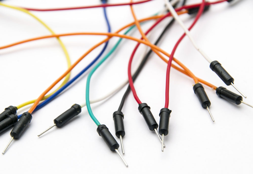
(Jumper cable wires)
- Relay Shield,
- USB 2.0 cable type A or B,
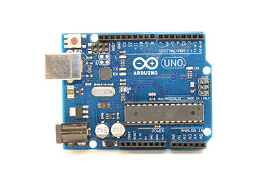
- Genuino UNO or Arduino UNO.

Shield Interface Description
There are four relays in a Relay Shield, that is, Relays 4, 3, 2, and 1. The pins for Relay Shield comprise;
Output pins; All four relays have three pins, namely COM, NO, and NC. Mostly, you’ll connect them to high-voltage devices regulated by a relay shield.
Explanation of output pin
NO (Normally Open): It disconnects to COM when the Relay1 control pin is set low but connects when Relay1 control pin7 is set high.
NC (Normally Closed): It disconnects to COM when the Relay1 control pin is set high but connects when the Relay1 Digital 7 I/O pin (control pin7) is set low.
COM (Common Pin): You can control it from the digital pin.
Signal pin/Input pin/Controlled pins; You’ll internally connect the controlled pins to Arduino pins during Arduino stacking. Hence, you won’t have to do any wiring.
The list below displays the type of pin control in each relay;
- Relay 4 – internally connected to Arduino pin12.
- Relay 3 – internally connected to Arduino pin8.
- Relay 2 – internally connected to Arduino pin7.
- Relay 1 – internally connected to Arduino pin4.
- Wiring diagram explanation
- The first step involves stacking your Relay Shield on an Arduino UNO board.
- Then, connect the above setup to a high-voltage device.
Remember:
You can use one high-voltage power adapter for the four devices controlled by a relay shield and a similar voltage. Contrarily, different voltages on the four devices will require dissimilar high-voltage power adapters.
Secondly, our setup operates on a normally open mode. Therefore, it’ll use NO and COM but not NC.
Relay Shield Example(s)/Usage
We’ll teach you how to use a Relay shield in the following section.
DC Motor Control
Steps
- Start by mounting the relay shield on your Arduino development board.
- Next, use a USB cable to connect the Arduino to a computer.
- We will now regulate DC motor using Relay3, then connect the relay shield and DC motor as it is in the diagram below;
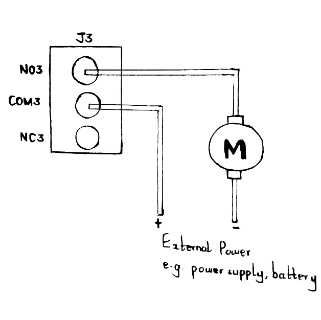
Schematic diagram showing a connection between a Relay Shield and Motor
Note; The external power supply utilized above should be from a power supply or battery like a lithium battery. Furthermore, you must set the correct voltage and provide enough current to the motor from the supply.
- The Arduino IDE you’ll upload on the Arduino board should be as follows;
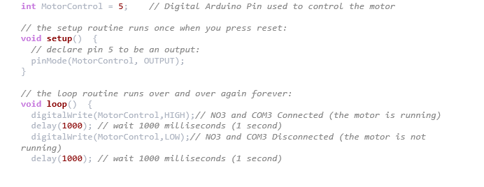
After uploading the code on the board, your motor will indeterminately start running for one second, stop for the next, then the process repeats itself.
As the motor works, NO3 LED indicator will light up since you’ve connected COM3 and NO3.

(LED stripe)
How to Use More Than One Relay Shield With Only One Arduino/Seeeduino Board
You can use several Relay Shields with one Arduino board since a relay shield controls each of its relays using Arduino digital pins.
Steps
- First, place one relay shield on your Arduino development board (Relay shield #1/ RS1).
- Secondly, use jumper wires/cables to connect relay shield #2/RS2 to relay shield #1.
- Then, connect;
- RS2 digital pins 4, 5, 6, and 7 to RS1 digital pins 11, 10, 9, and 8, respectively.
- RS2 5V pin to RS1 5V pin.
- RS2 GND pin to RS1 GND pin.
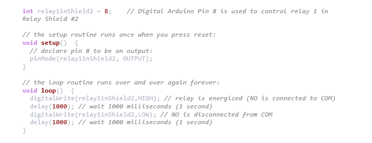
- Finally, you can use Arduino’s 11, 10, 9, and 8 digital I/O pins to control RS2’s control relays 4, 3, 2, and 1.
The code below shows how you’ll control relay1 in RS2.
Conclusion
Briefly, a relay shield offers a solution for regulating high-current devices that the digital I/O pins of Arduino don’t normally restrict.
Relay shields have a large scope in technological learning. Therefore, if you have any questions or need assistance, don’t hesitate to contact us.


