Contents
How Does the Audio Mixer Circuit Work?
Generally, an audio mixer circuit works by following the procedure below;
- First, it receives audio signal input from various sources such as CD players, PC sound cards, and microphone inputs.

(microphone giving audio input signals)
- Then, it combines the signals from the sources and acts as the volume control system. It does so by changing the volumes of each input signal and the entire mixer output volume.
Audio mixer circuits help in audio equalization by boosting the frequencies.
Five Simple Audio Maker Circuits Explained
Examples of audio maker circuits are as follows;
4-channel Audio Mixer using a Single Op-Amp
For the first audio maker circuit, we’ll incorporate an IC LM3900. LM3900 is in a 14-pin dual inline package. Then, in the list of LM series, it is a Quadruple Norton Op-Amp IC. Additionally, its supply voltage varies widely from 4.5V to 32V. Also, it has an internal frequency compensation.
The circuit only gives a minimum gain for the mixed audio output signal. Therefore, you can add an external amplifier to help with strengthening the audio signal.
4-channel audio mixer circuit using Op-Amp
How it Works
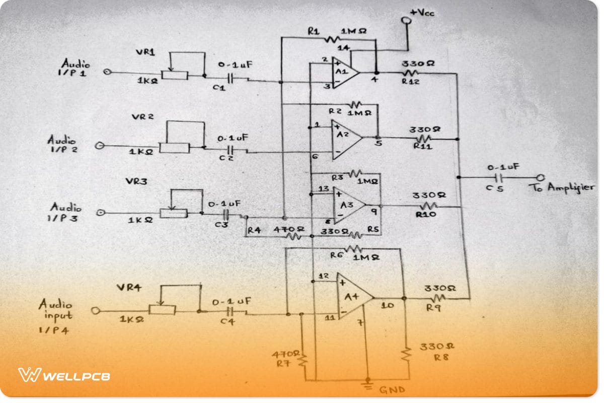
Consider the simple circuit diagram below for an elaborate explanation;
- Here, the operational amplifier stage is LM3900. All the internal amplifiers (A1-A4) work by amplifying the audio input signals.
- Then, VR1 to VR4 (variable resistors) control the audio input from the four channel-mixer sources. Thus, the process makes it easy to regulate each audio channel.
- Next, the amplifier’s inverting input gets the audio signals and proceeds to ground the non-inverting pins. You can use a 1M resistor to achieve a feedback setup.
- Lastly, there’s an output signal combination and emission for the purpose external power amplifier.
Notes on IC LM3900
LM3900 IC has 14 pins for the four operational amplifiers in the internal circuit. Often, every amplifier has non-inverting, inverting, and output pins, ground pins (VCC), and power supply pins (GND). The same case in pinout applies to the LM3900.
The four internal amplifiers operate self-reliantly and get a compensation of high gain frequency. Additionally, you’ll only need a single power supply source and can work with a split supply. Most importantly, it has a wide bandwidth, and the output voltage swing is excellent.
Parts List
They include;
- A1-A4 are LM3900 IC,
- C1-C5 – 0.1Uf,
- VR1-VR4 – 1KΩ,
- R5, R8-R12 – 330Ω,
- R1, R2, R3, and R6 – 1MΩ,
- R4, R7 – 470Ω
Simple FET Audio Mixer Circuit
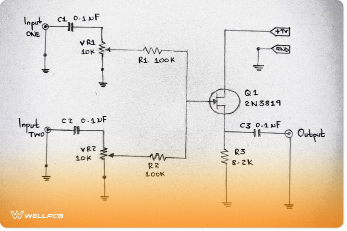
In this second audio mixer circuit, FET number 2N3819 acts as the main. Generally, it has a high gain and high impedance input, therefore producing less noise. The features also make it more efficient than standard transistors. Further, you can add a needed amount of R1, C1, and VR1 to increase its channel number. Then again, it uses a low current, such as 9V, for its operation.
Audio Mixer with LF353 circuit
Working principle
- First and foremost, the audio signal enters the circuit through inputs 1 and 2.
- Secondly, C1 and C2 transmit the signal to VR2 and VR1.
- Also, you can use FET Q1 to adjust the audio signal.
- Finally, the modified signal goes through C3 and then gets transmitted as an output signal at output pin S.
Audio Mixer by IC LF535
It uses a 4-channel audio mixing signal. The IC here is an LF353, and it is the leading electronic component in the circuit. Also, LF535 is in combination with the 4-channel series at the upper signal level. The circuit diagram below explains the concept.
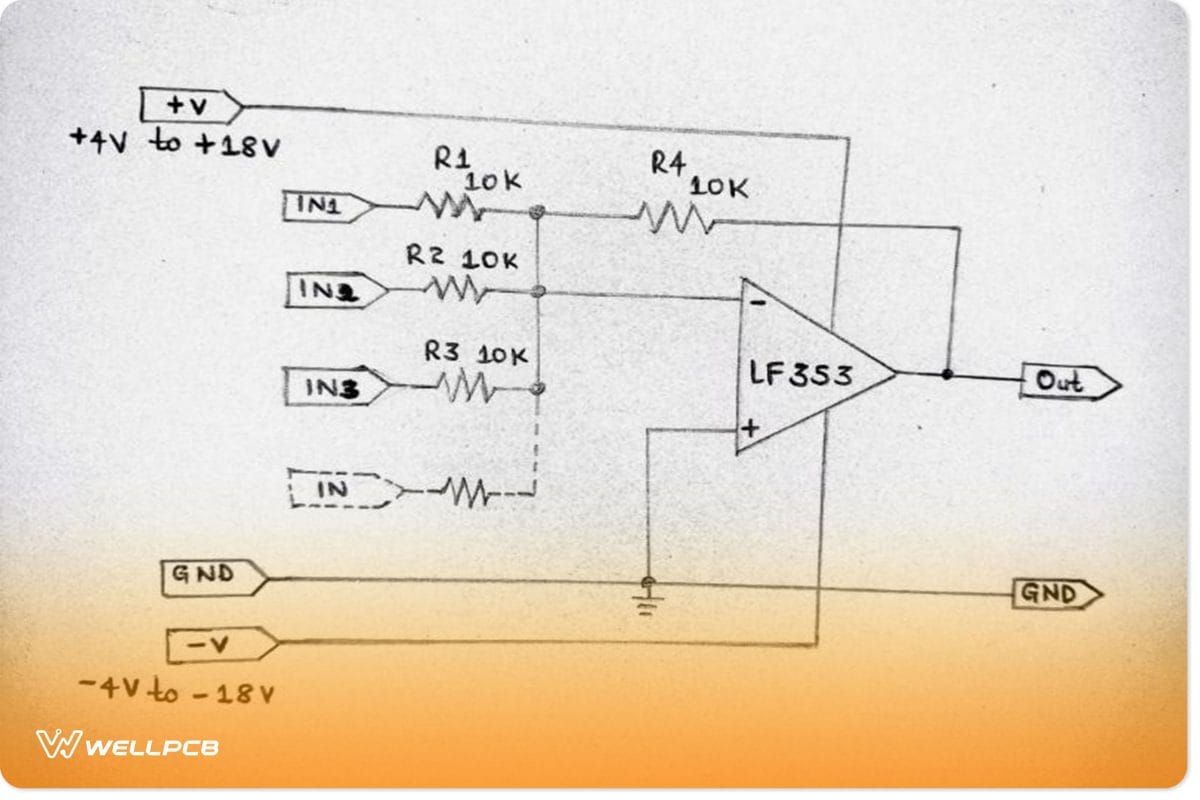
Audio Mixer with LF353 circuit
3 CH MIC preamplifier with Mixer using LM348
You can use a 3-channel microphone amplifier circuit to make a mixer with a microphone. Also, it is cost-effective since you won’t have to use four pieces of IC—741 ICs. Instead, you’ll use a single IC LM348. Further, you can freely adjust each microphone’s volume via VR3, VR3, or VR1. Most importantly, its power regulator has a dual power supply of -12V/ +12V and DND. In addition, it is a DC voltage regulator type having a transistor, IC7912 or IC7812, as per your requirement.
Note; Using a pre-amplifier before proceeding from a single to the power amplifier is essential, and it is because the circuit has a low output power.
Micro Mixer Circuit using TA7137
For the micromixer circuit using TA7137, you can use approximately four input channels. They include AUX, microphone signals, FM tuners, and other varied signals. Besides, it has a miniature size, good versatility, and is affordable.
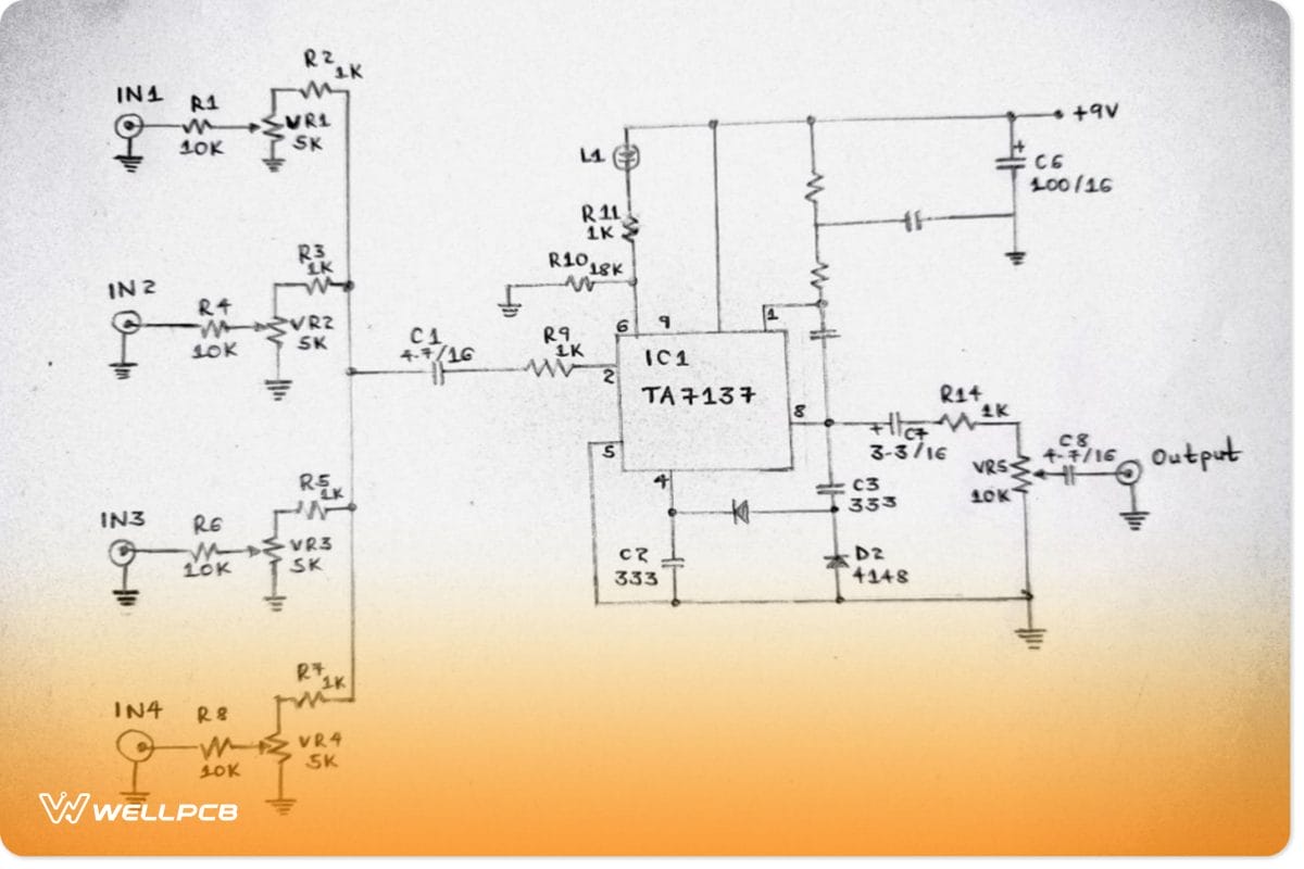
Micro mixer circuit diagram using TA7137
How it Works
- TA7137 (IC1) is the amplifier signal that results in an output signal at pin8 from C7.
- Then, VRF and R14 often adjust the total output signal strength.
- Further, D2, D1, C3, and C2 function as a feedback circuit system. And, they help control circuit gains to ensure a constant level of the output voltage signal.
- Lastly, the L1 LED operates as the signal meter display. As such, when you apply an input voltage to the circuit, the signal strength will make it flash.
First and foremost, potentiometer VR1-VR4 receives an input signal from every channel via R1, R4, R6, and R8. Often, they act as input resistors and accept the call in that order (R1-R8). Next, through R2, R3, R5, and R7, the signal frequencies will reach the input of IC1 via R9 and C1.
Microphone Components/Parts List
- IC1 – TA7137 preamplifier (it should be playing back or recording with an ALC transistor as the tape recorder)
- L1 – LED with a 2×5mm measurement
- VR4, VR3, VR2, and VR1 – 5K-10K, potentiometer
- VR5 – SW 10K
Diodes
- D2 and D1 – 75V 150mA diodes, 1N4148
0.25 resistors with a tolerance of 5%
- R12, R8, R6, R4, and R1 – 10K (are the input resistors)
- R14, R9, R7, R5, R3, and R2 – 1K
- R11 – 18K
- R10 – 1K
Polyester and electrolytic capacitor values
- C7 – 3.3uF 16V electrolytic
- C6 – 100uF 16V electrolytic
- C5 – 47uF 16V electrolytic
- C4 – 30pF 63V polyester
- C3 and C2 – 0.0033uF 50V polyester
- C8 and C1 – 4.7uF 16V electrolytic
Conclusion
In conclusion, the article summarizes five simple circuits that you can try out when wanting to make an audio mixer. A mixer circuit can mix two different signal channels, with one being an output channel. Then again, you can use a codec circuit to get a mono audio time from stereo audio.
That’s it for today. For more information on audio mixer circuits, kindly contact us.