An automatic day-night on-off switch can be helpful for a myriad of purposes as street lights or a simple college project. Join us as we discuss how an automated switching system works at length.
Contents
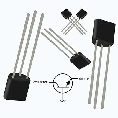
Light Activated Day Night Switch using Transistors
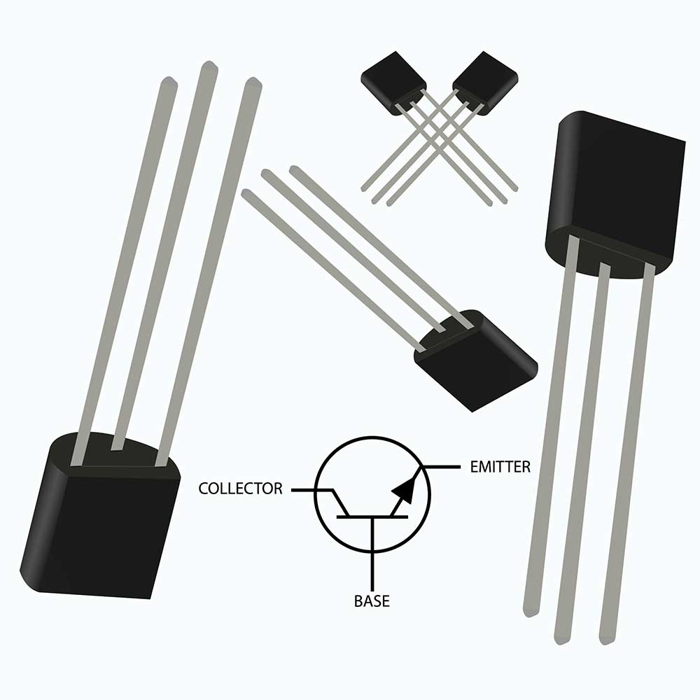
Fig 1: A Transistor
Critical Components of the Circuit
- Relay- 12V, 400 ohms, 5A
- Resistors- R1, R2, R3 (4k7 1/4 watt)
- Capacitors- C1 and C2 (470uF/25V and 10uF/25V)
- Small LDR with a resistance of 10K to 50K
- 1N4007 Diodes
- 10K Preset/ Trimmer
- Transistors- T1 and T2 (BC547)
Circuit Explanation
Notably, the transistors in this circuit operate as inverters; thus, when one of the transistors is on, the other one is off. Also, in the course, one of the transistors is a comparator and features a light-dependent resistor (LDR) in its base, and the positive supply connects to a preset.
Further, it has an LDR that detects ambient light conditions. In turn, the LDR prompts the action of the transistor if the surrounding light levels cross a set threshold. The preset in this circuit is handy in setting up the desired point.
Also noteworthy, the two transistors prevent circuit hysteresis, which is probable suppose you use one transistor. Moreover, when the first transistor is on, the other is off, as earlier mentioned. Also, this is the relay’s behavior and the connected load/light.
Lastly, the reverse will happen when night mode sets in.
Light Activated Day Dark Switch using CMOS NAND gates and NOT Gates
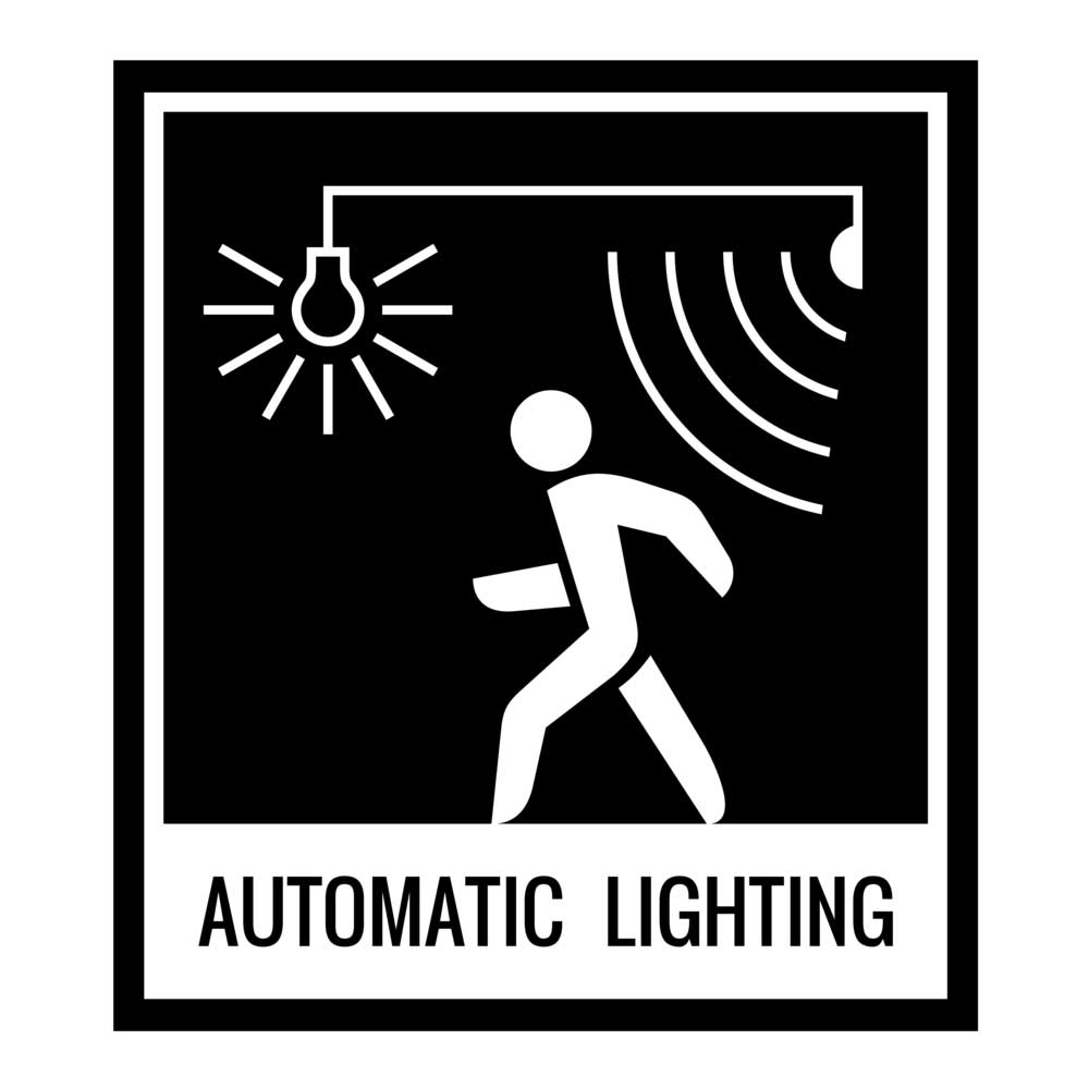
Fig 2: An illustration of an automatic light control system.
Key Components
- An LDR with a 10k to 50k resistance in daylight (R1)
- A 1M preset (P1)
- A 0.1uF ceramic disc capacitor (C1)
- A 10k 1/4 watt resistor (R2)
- BC547 (T1)
- A 1N4007 diode (D1)
- A 12V, 400 ohm 5A relay
- An IC 4093 or IC 4049
Circuit Explanation
Shorting the inputs of the gates converts them to inverters. It is handy in enabling the gates’ input logic level to reverse at the outputs. Also, you can use a single NAND gate (NOT-AND), but using three gates makes the additional ones buffers for better circuit performance.
The sensing gate features a light sensing device LDR on its input and a variable resistor on its positive. Essentially, the variable resistor aids in setting the gate’s triggering point once the light on the LDR attains a particular light intensity.
At the same time, the gate input is high while the output goes low, which renders the buffer gates’ results tall. Consequently, this triggers the transistor and the relay assembly.
Lastly, the connected load on the relay produces the desired action.

Light Activated Relay Switch using IC 555
Circuit Diagram

Fig 3: Circuit Diagram
Key Components
- Resistors- Rx, Rz, and Ry = 100k, 100K, and 2m2, respectively.
- Capacitor- Cx- 0.1uF
- Rl1- 12V, SPDT,
- A 1N4007 Diode- (D3)
- N1- IC 4049
- N1- IC 4093, IC1 = 555
Working Principle
This circuit works similarly to the former automatic lighting system we’ve just analyzed, only that in this case, you’ll use an IC 555.
Automatic Night Operated LED Lamp Circuit
Circuit Diagram
Below is a simplistic representation of this kind of circuit.

Fig 4: Circuit Diagram
It’s the design behind the electrical devices with high-efficiency LEDs that are common in the market today.
Circuit Parts
- A PNP BC557A
- A 1K resistor
- A phototransistor
- One super bright white LED
- One 3V battery
Circuit Explanation
A phototransistor is handy in making the valuable circuit for outdoor lighting at night times. Hence, the LED will switch on whenever the daylight is gone. Furthermore, a one-button battery is imperative in compacting the circuit.
When ambient light hits the phototransistor, its emitter lead’s voltage is relatively high. Consequently, the PNP transistor remains off.
However, the phototransistor conduction diminishes once there’s darkness, and similarly, its emitter lead’s voltage also drops. At last, the phototransistor goes off.
At the same time, the PNP transistor starts biasing, prompting it to light up as the ambient light dims.
Notably, the resistor in the circuit facilitates setting the desired ambient light at which the LED should switch on. You may opt to use a potentiometer for your college project, but it’ll affect the sleekness of the automatic day-night sensor unit.
Lastly, the circuit will use about 13 mA when the LED is on and significantly lesser current when it is off.
Conclusion
There are various variations of auto-sensor lighting products, but we’ve covered the basics. Reach out to us for queries on the day-night automatic lamp and other related topics.


