Contents
What is a Battery Backup Circuit?
Battery backup circuits are circuit types that immediately shift the load to the battery when there’s no main supply. However, if there’s a main supply, the load shifts to the power supply as the backup battery enters charge mode.
You’ll mostly find the battery backup circuit in applications comprising surveillance systems like alarm operation. Thus, whenever the mains in the course fail, the battery backup instantly picks up the load.

(home security alarm)
Schematic Diagram of the Battery Backup Circuit
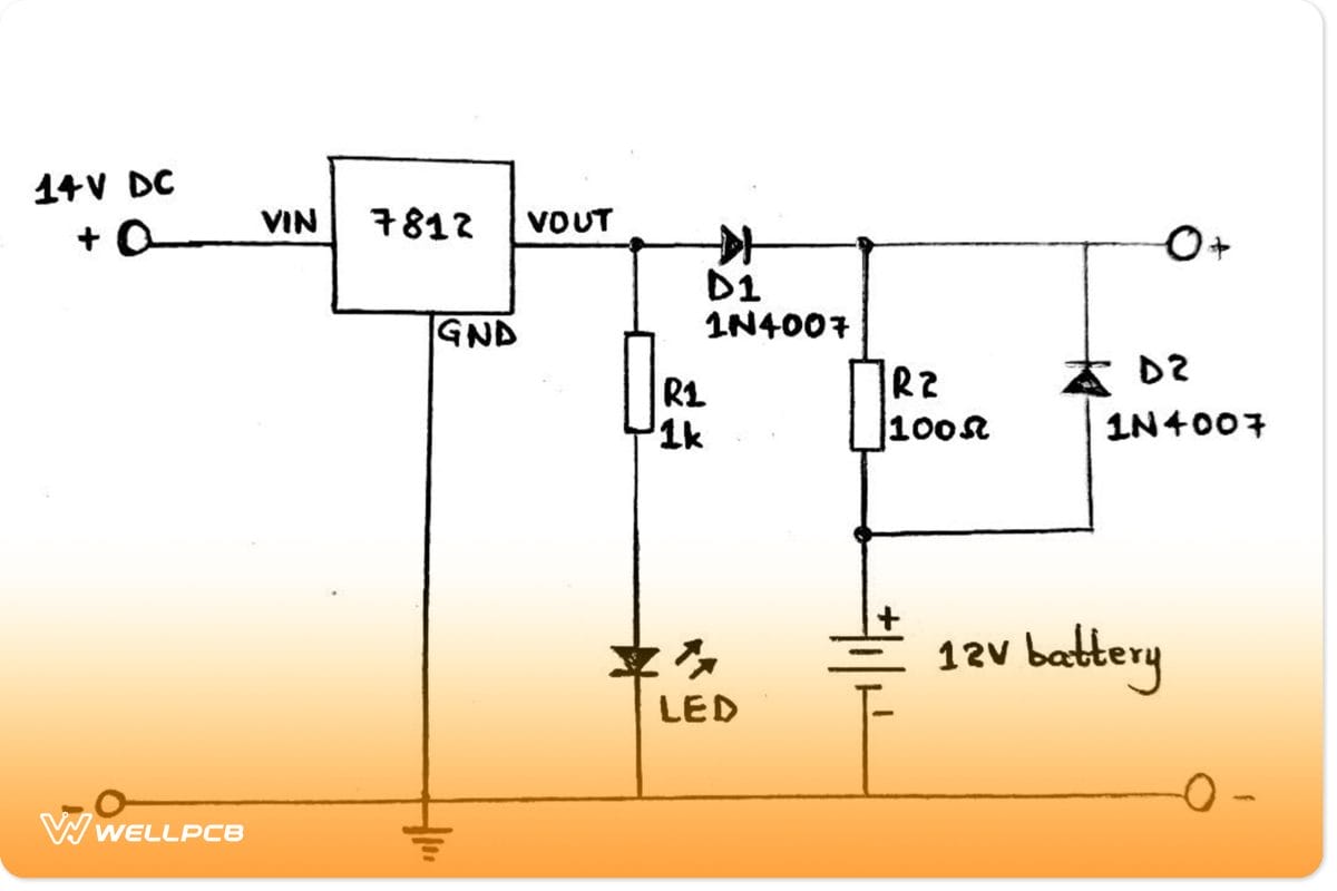
Schematic diagram of a battery backup circuit
The diagram gives a simple circuit of battery backup. And in terms of functioning;
- The 7812 IC provides 12V of regulated DC to power the circuit. In addition, it charges the rechargeable battery.
- Then, the LED shows the power status.
- If the mains supply is available, D1 will forward bias and then pass current to the battery via R2. In our case, the value of R2 should give a 90mA current to help in slow charging.
- However, without the mains supply, D2 forward biases and D1 reverse biases. Consequently, it backs up the circuit.
Create your Battery Backup Circuit
Now, let’s make our battery backup circuit using the examples below.
12V power supply with battery backup circuit
We’ll use a 12V power supply to make a battery backup circuit for our first DIY project. When there are power-supply voltages, the load shifts to that main supply as the battery goes into automatic charging mode. However, when there’s no mains supply, the circuit will automatically shift the current load to the battery – a backup method.
Materials to be prepared
The hardware components for the circuit include;
- A battery – 12V 7.2AH,
- Zener diode – 9.1V or Schottky diodes for low voltage, i.e., 0.4V,
- LM812 IC,
- Relay – 12V
- Green LED,
- Step-down transformer – 110V or 230V AC to 12V/1mA,
- 4 Bridge rectifiers – 1N4007,
- Capacitors – 1000µF/50 V, 330µF, 100nF,
- Resistors – 1KΩ (3 pieces), 10KΩ, 470RΩ,
- Switch,
- Transistor – 2N4401, 2N4403, and
- two pieces of a diode for both 1N4007 and 1N4148.
Circuit diagram

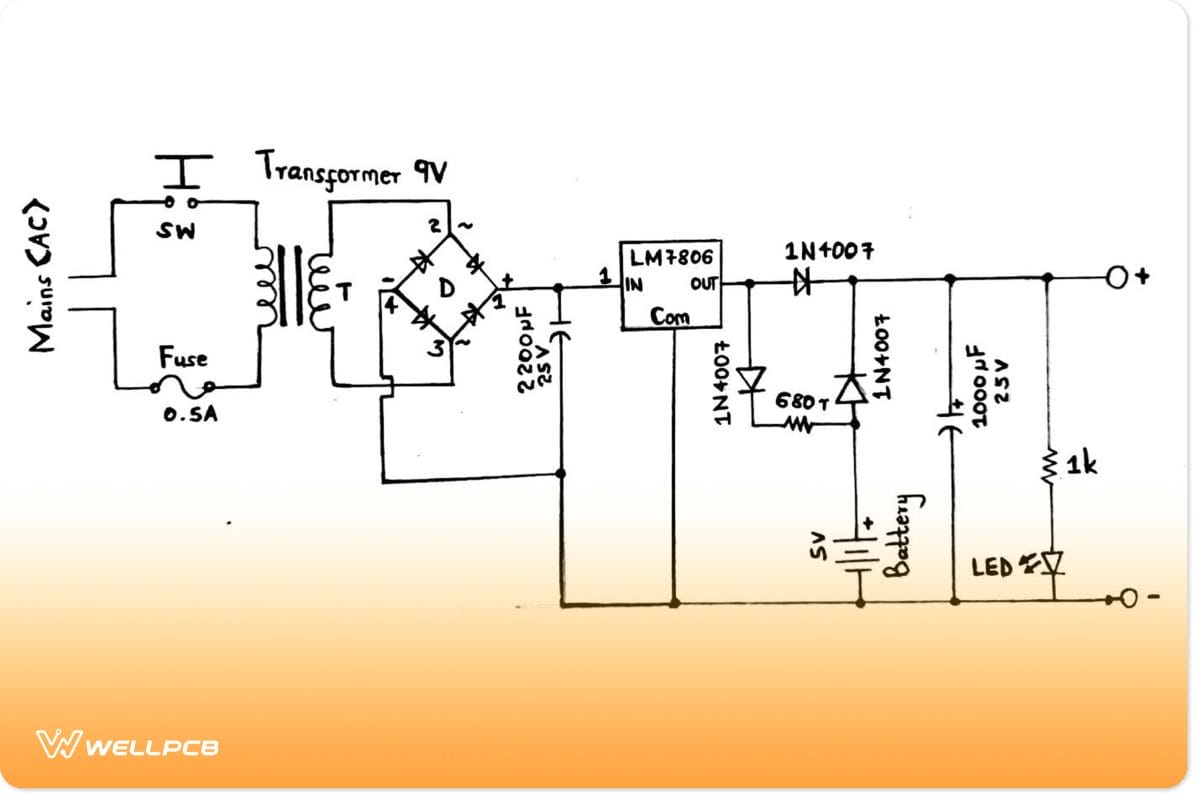
Circuit diagram of a 12V power supply with battery backup
Principle of operation explained
The circuit above comprises three parts for this advanced switch mode technology of 12V power supply.
- The first part involves a step-down transformer that supplies power to the battery backup circuit.
- The second has an automatic battery charger, 12V 7.2AH. Alternatively, you can use 12AH or 10AH for a longer battery backup. 25 or 20 AH SLA batteries are also recommendable, although they take longer to charge, thus decreasing the backup time. For example, a 20AH discharged battery can take up to 20 hours to fully charge.
When the battery gets fully charged, the circuit will stop working instantly. Also, the green LED here indicates if you’ve got a fully charged battery.
- The third part is the voltage regulator. It uses smoothing capacitors and IC LM812 to provide a clean and fixed backup voltage of 12V.
The circuit produces an output current of 1A that suits devices working under a current of 1A.
You can modify the circuit using suitable diodes and a high-amperage transformer to get an even higher current. In addition, an IC transistor can change the output current. Eventually, the circuit will charge up the higher amperage battery quicker.
Notes on circuit adjustment
Before using the circuit, you’ll need to make some adjustments.
- First, connect the circuit to an adjustable power supply voltage of 14.4V.
- Then, remove the transformer and battery. After that, connect the power supply where you initially had the battery.
- Keep on adjusting the 10K variable resistor till the green LED glows.
- The fourth step involves replacing the adjustable power supply with your original transformer and battery. Your circuit will enter into a charging mode.
- While it’s charging, check if the LED glows when the battery voltage gets to 14.4V. You can also use a multimeter to check the voltage. If the LED doesn’t light up, adjust the 10K variable resistor till it does.

(LED bulb)
- Your circuit is now ready for use.
Simple 5V backup battery circuit
The simple 5V circuit is applicable in microcontroller projects where you need to maintain a current source without disruptions.
Simple circuit with a 5V backup battery
Its operation is as follows;
When the main fails, the battery automatically takes the load. Then, when the main starts working, the battery switches to a charging mode.
An Alternative Form of Backup
A battery backup often gets into a state of standby when the main power flops. However, only alarm sections of your system or critical volatile memory receive power. As such, you’ll need an oversized battery to carry data in length outages.
Conversely, the capacitor-based backup systems provide continuous power when the main power fails. In that way, the system will transfer volatile data into flash memory using short-term backup power. But you’ll need additional safety features to ensure capacitors don’t exceed their maximum voltage in the charging mode.
Conclusion
A backup battery works by alternating from a charging mode to a backup method. With proper care, like medium temperature and moisture, your backup battery can last you for 3-5 years for backup power.
Are you planning on doing the project(s)? How about you contact us with the technical questions for more guidance when stuck? We’ll be more than happy to help.