Contents
What is a BC558 Transistor?
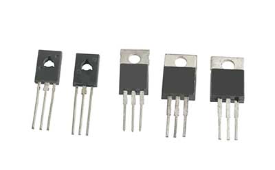
BC558 transistor is a BJT in a TO-92 package used for switching and amplification purposes. It is from the family of PNP transistors.
For a better outcome with the BC558 transistor, ensure you don’t use a drive load that exceeds 30V. Then, check and apply a suitable base resistor.
BC558 transistor Pin Configuration
BC558 transistor has three terminals/pins. They comprise the collector, base, and emitter.
- Pin1/ Collector pin allows inward current flow.
- Then, pin2/ Base pin regulates the transistor’s biasing.
- Finally, the pin3/ Emitter terminal drains out the current.
BC558 Features
The features and specifications of the BC558 transistor are as follows;
- First, it has a continuous maximum collector current of 100mA and a peak collector current of 200mA.
- Additionally, the maximum collector-emitter voltage and collector-base voltage are at 30V. Conversely, the maximum emitter-base voltage is 5V.
- The base current is also at a 200mA peak.
- Then, its maximum collector dissipation is 500 mW (Milliwatts), whereas its maximum transition frequency is 100MHz.
- Further, the maximum storage and operating temperature should range from -65°C to +150°C.
- The minimum to maximum DC gain ranges from 110 to 800.
- Finally, it has a through-hole mounting type, with a package type like TO-92-3 and TO-226-3.

The Working Principle of BC558 Transistor
Briefly, BC558 uses the mechanism below to operate.
In the absence of current at the base terminal, the collector and emitter will close. Consequently, the transistor turns on because of its now forward-biasing mode.
On the other hand, the current at the base keeps both the collector terminal and emitter open. In that way, the transistor is in a reverse-biased mode.
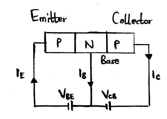
Circuit diagram of the BC558 transistor structure and working
Key points
- The base side controls the transistor’s conductivity, whereas the emitter transfers the transistor’s current.
- Moreover, the collector and emitter are +ve while the base is -ve.
- Thirdly, a biased transistor allows a continuous current flow of 100mA crossway between the emitter and controller (Saturation region). In the stage of saturation region, the voltage across the base-emitter can be 900mV while the one on the collector-emitter can be 200mV.
- Contrarily, removing the base current causes the transistor to go into the Cut-off region stage. Here, the base-emitter voltage approximates 660Mv.
For further details and comprehension, let us consider two ways to use the BC558 transistor.
BC558 as switch
We’ll start by employing the stages of Saturation and Cut-off region.
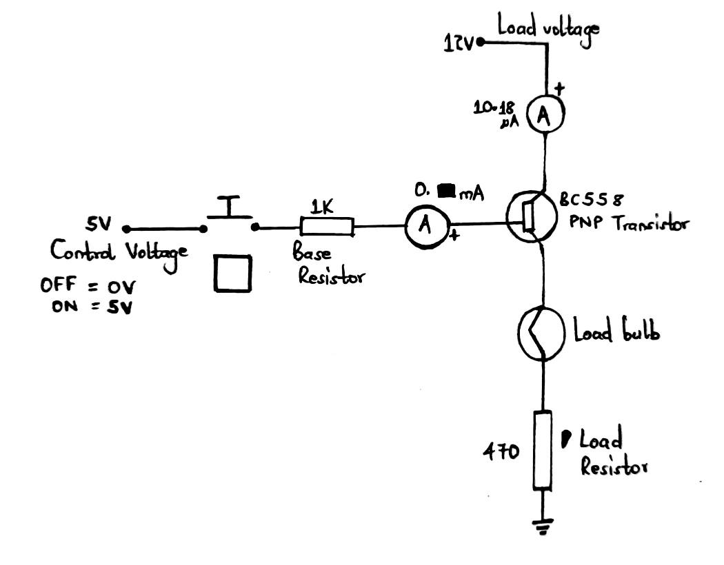
BC558 transistor as a switch in a circuit
It applies the working principle whereby the transistor is a closed switch during reverse bias and an open button during forwarding bias. The biasing is due to the base pin receiving a required current flow.
Furthermore, you’ll need a resistor in series with the base terminal to restrict the base current.
The formulae below can help you calculate the resistor value;
RB = VBE/IB
RB = Resistor
IB = Base current
VBE = Emitter base voltage (should be 5V)
Generally, the PNP transistor operates as high-side switching. In other words, you connect the emitter to the load for switching and the collector to power.
BC558 as Amplifier
The Active Region is where the BC558 will act as an amplifier. The transistor will amplify current, voltage, and power at different configurations.
Examples of the configurations;
- Common base amplifier,
- The Common collector amplifier,
- Common emitter amplifier (most common type).
Most tech enthusiasts use BC558 in audio amplifiers. Its mechanism of action is such that low-voltage input signals get amplified to higher voltages for driving loads.
The formulae below can help us calculate the DC gain of the transistor;
DC Current gain = Collector current (IC) / Base Current (IB)
What can I use Instead of a BC558 Transistor?
A BC558 transistor, like other transistors, has alternatives or replacements.
They include; BC157, BC557, A1015, BC556, BC559, 2N4403, 2N3906, BC338, TIP127, BD140, TIP42, S8550, and BC337.
In addition, you can complement it using an NPN transistor like BC548.
Note;
Always check the pinout of alternative transistors, as they might contrast with the BC558 pinout.
Applications
The applications of a BC558 transistor include;
- General-purpose amplifier,
- Darlington pair,
- As a preamplifier and for switching purposes,
- Current mirror circuits and H-bridge circuits,
- As an impedance buffer,
- Oscillator and comparator circuits,
- Amplifier modules like a signal amplifier and audio amplifier,
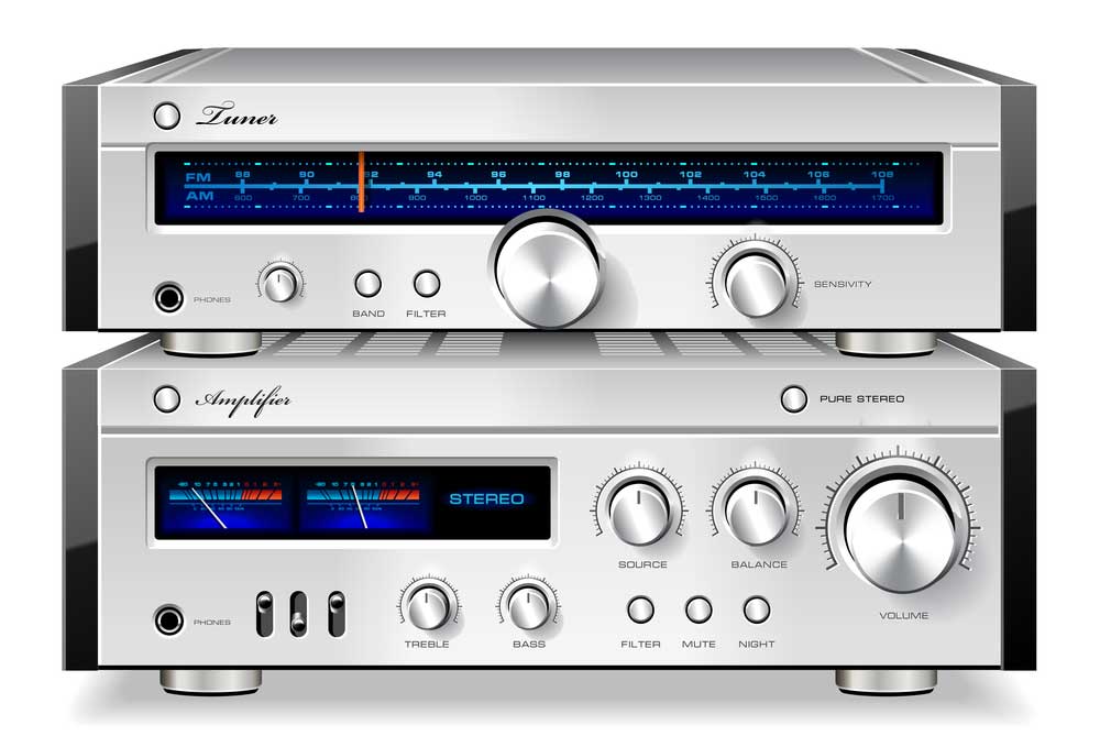
(music stereo audio amplifier).
- For building audio signals,
- Driving loads of less than 100mA,
- Controlling motors,
- In constructing bistable and astable multivibrators,
- Instrumentation projects and robotics,
- Lastly, you can use it in driver modules like an LED driver and a relay driver.
Conclusion
In summary, the BC558 transistor is a PNP transistor made of silicon material common for audio amplification purposes. It acts as a current control device as the base terminal converts small currents into larger currents in other airports.
We hope that you’re well-versed with the BC558 transistor. Nonetheless, in case of any questions or clarifications, kindly contact us.


