Contents
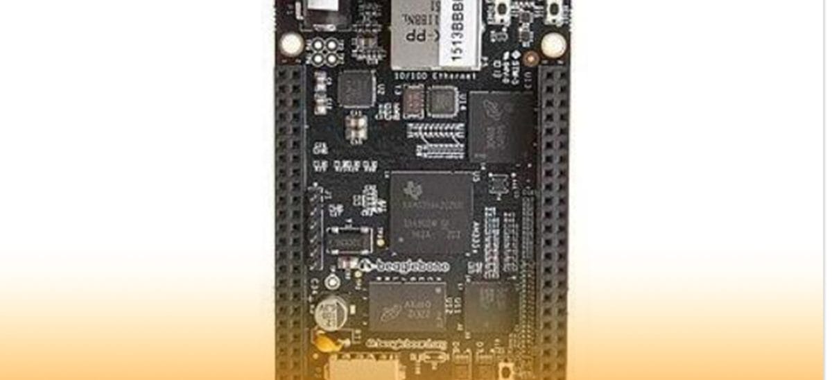
BeagleBone Black Pinout pin configuration
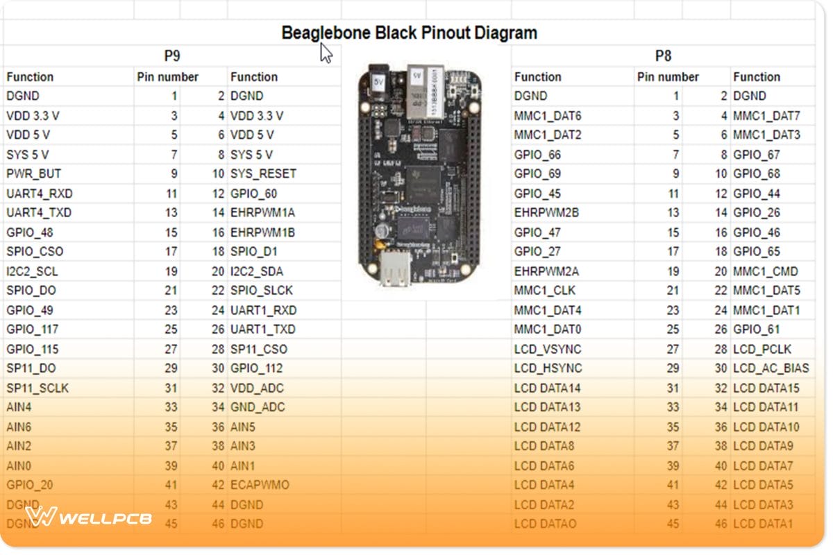
Beaglebone black pinout arrangement and configuration
There are two expansion headers in beaglebone black. Specifically, the headers, namely the P8 header and P9 header, each header having 46 pins and giving a total of 3.3V per header.
Power input pins: The BeagleBone Black circuit board has two further inputs: a USB port and a DC power jack.
Power output: There are also three output power pins on the BeagleBone, which can also help external power devices.
Pin one offers 3 Volts, and its energy comes from Low Dropout (LDO), and it could even be helpful for max 250mA current score devices. It is also advisable to use an external power source if there is an ampere increase.
Power port two offers 5 volts maximum output, which also comes without delay from the direct current Jack electricity delivery pin.
Here is the list of pins according to voltage output in the P9 header:
- 3.3 V are Pin4 and Pin3
- +5 V(VDD) are Pin6 and Pin5
- +5 V(SYS) are Pin8 and Pin7
Ground pins:
Beaglebone black additionally contains more ground pins to facilitate the smooth operations of the pins. Subsequently, some of these pins have an internal connection with different peripherals all connected.
• P8 digital ground(DGND) pins – Pin46, Pin45, Pin44, Pin43, Pin2, Pin1.
• P9 digital ground(DGND) pins– Pin 1, pin 2
Power Button: The power button comes in handy as it allows for the powering and shutting down of the entire circuit board.
• Power Button – Pin9
It allows for an orderly closedown of the device through an outside pulse using saving all statistics.
Reset Button: This tool has an outside reset button that restarts the circuit board competently. Thus P9 Header acts as the reset. The pin is in the list below:
• SYS_RESET – Pin 10
General Purpose Input/Output (GPIO Pins)
There are nearly 69 digital GPIO pinout pins in the device. However, some of them can also be useful in different predefined functions. Subsequently, 3.3V can pass on all of the I/O pins. All the I/O pins on the BeagleBone Black are in the list below:
| p8 | p9 |
| GPIO_30 – Pin11GPIO_60 – Pin12GPIO_31 – Pin 13GPIO_40 – Pin 14GPIO_48 – Pin 15GPIO_51 – Pin 16GPIO_4 – Pin17GPIO_5 – Pin18GPIO_13 – Pin19GPIO_12 – Pin20GPIO_3 – Pin21GPIO_2 – Pin22GPIO_49 – Pin23GPIO_15 – Pin24GPIO_117 – Pin25GPIO_14 – Pin26GPIO_125 – Pin27GPIO_123 – Pin28GPIO_111 – Pin29GPIO_112 – Pin30GPIO_110 – Pin31GPIO_20 – Pin41GPIO_7 – Pin42 | GPIO_38 – Pin3GPIO_39 – Pin4GPIO_34 – Pin5GPIO_35 – Pin6GPIO_66 – Pin7GPIO_67 – Pin8GPIO_69 – Pin9GPIO_68 – Pin10GPIO_45 – Pin11GPIO_44 – Pin12GPIO_23 – Pin13GPIO_26 – Pin14GPIO_47 – Pin15GPIO_46 – Pin16GPIO_27 – Pin17GPIO_65 – Pin18GPIO_22 – Pin19GPIO_63 – Pin20GPIO_62 – Pin21GPIO_37 – Pin22GPIO_36 – Pin23GPIO_33 – Pin24GPIO_32 – Pin25GPIO_61 – Pin26GPIO_86 – Pin27GPIO_88 – Pin28GPIO_87 – Pin29GPIO_10 – Pin31GPIO_11 – Pin32GPIO_9 – Pin33GPIO_81 – Pin34GPIO_8 – Pin35GPIO_80 – Pin36GPIO_78 – Pin37GPIO_79 – Pin38GPIO_76 – Pin39GPIO_77 – Pin40GPIO_74 – Pin41GPIO_75 – Pin42GPIO_72 – Pin43GPIO_73 – Pin44GPIO_70 – Pin45GPIO_71 – Pin46 |
BB UART Communication
It is the most famous serial communication pin for most structures and gadgets. Consequently, in this type of communication, separate pins are for the transmission and receiving of data.
P8 header:
UART5_TX – Pin37
UART_RX – Pin38
P9 header:
UART1_TX – Pin24
UART1_RX – Pin26
UART2_TX – Pin21
UART2_RX – Pin22
UART4_TX – Pin11
UART4_RX – Pin13
Serial Peripheral Interface (SPI) communication Pins
SPI verbal exchange pins in the BeagleBone Black are two. However, all of those Serial Peripheral Interfaces have a separate slave pin header. Consequently, due to more than one slave pin, each device can also speak with two special types of Serial Interface protocol devices. Both SPI communique pins are in expansion Header P9:
SPI0_CS0 – Pin17
SPI0_D0 – Pin21
SPI0_D1 – Pin18
SPI0_SCLK – Pin22
SPI1_CS0 – Pin28
SPI1_D0 – Pin29
SPI1_D1 – Pin30
SPI1_SCLK – Pin31
I2C Communication Channels
The circuit board has two I2C communications channels, which all are in the P9 growth Header:
I2C1_SCL – pin 17
I2C1_SDA – pin 18
I2C2_SCL – pin 19
I2C2_SDA – pin 20
Pulse-width modulation (PWM) Channel Pins
TAdditionally, BeagleBone Black produces a rectangular output pulse to operate cars and other capable gadgets. It also includes numerous pulse-width modulation pins that generate the output sign using timers and a Prescaler.
Multichannel Audio Serial Port (MCASP )
It’s also for serial port programs with several channels. It uses the clock, statistics, and frame sync pins that are all on their own. In BeagleBone, the MCASP pins are found in P9, namely.
MCASP0_FSX (Frame Sync) – pin 29
MCASP0_ACLKX (Clock Sync) – pin 25
MCASP0_AHCLKX (Data out) – pin 31
MCASP0_AXR2 (Data in) – pin 28
Multimedia Controller (MMC) Pins
The embedded 2GB multimedia controller on the BeagleBone Black allows the device to run off its internal eMMC rather than an SD card. Hence, the MMC1 is a standard boot method that connects directly to the processor port. However, because the internal multimedia controller is 8-bit and permits specified sorts of pins to operate, this also renders the default mode unusable in the case of a memory card. MMC1 pins are also found in header P8:
MMC1_CMD – Pin20
MMC1_CLK – Pin21
MMC1_DAT0 – Pin25
MMC1_DAT1 – Pin24
MMC1_DAT2 – Pin5
MMC1_DAT3 – Pin6
MMC1_DAT4 – Pin23
MMC1_DAT5 – Pin22
MMC1_DAT6 – Pin3
MMC1_DAT7 – Pin4
Analog to virtual Converter Channels
BeagleBone instantly converts analog signals into digital symbols. It features seven Analog Digital (A/D) channels using the same 12-bit Analog-Digital Converter (ADC) channel. It desires an activation first via delivering 1.8V electricity through ADC strength pins. The ADC and electricity pins locations are in the P9 expansion header.
AIN0 – pin 39
AIN1 – pin 40
AIN2 – pin 37
AIN3 – pin 38
AIN4 – pin 33
AIN5 – pin 36
AIN6 – pin 35
VDD_ADC – pin 32
GND_ADC – pin 34
BeagleBone Timers Module Pins
In BeagleBone Blacks, four internal timer pins used with the external pulse input ports are in the P8 header.
TIMER1 – Pin10
TIMER2 – Pin9
TIMER4 – Pin7
TIMER7 – Pin8
BeagleBone Black Technical Specifications
A picture of BeagleBone Black Technical Specifications
SDRAM Memory – 512 MB DDR3L 800MHz
Graphics engine –SGX530 3D 20M polygons
Onboard flash – 4GB 8-bit Embedded MMC
Power source – 5V DC External via expansion header<6 layers>
-mini USB
Video -16b HDMI 1280x 1024 MAX
Audio – HDMI
Difference Between BeagleBone Black and BeagleBone
• Processor: You can also think of the processor as your BeagleBone’s “brains.” While both processors function like the ARM Cortex-A8, Beaglebone operates with a maximum speed of 720MHz, while BeagleBone Black has a maximum speed of 1GHz.
• RAM: An authentic BeagleBone Black has 512MB of DDR3, whereas BeagleBone has 256MB of DDR2 (Double information fee 2).
• MicroSD card slot: The authentic BeagleBone constantly needs to have a microSD card inner for you to work. Usually, it comes with a default 4GB microSD card, and the BeagleBone Black comes with built-in memory and doesn’t come with a microSD card.
BeagleBone Black Block Diagram and 2D Chart
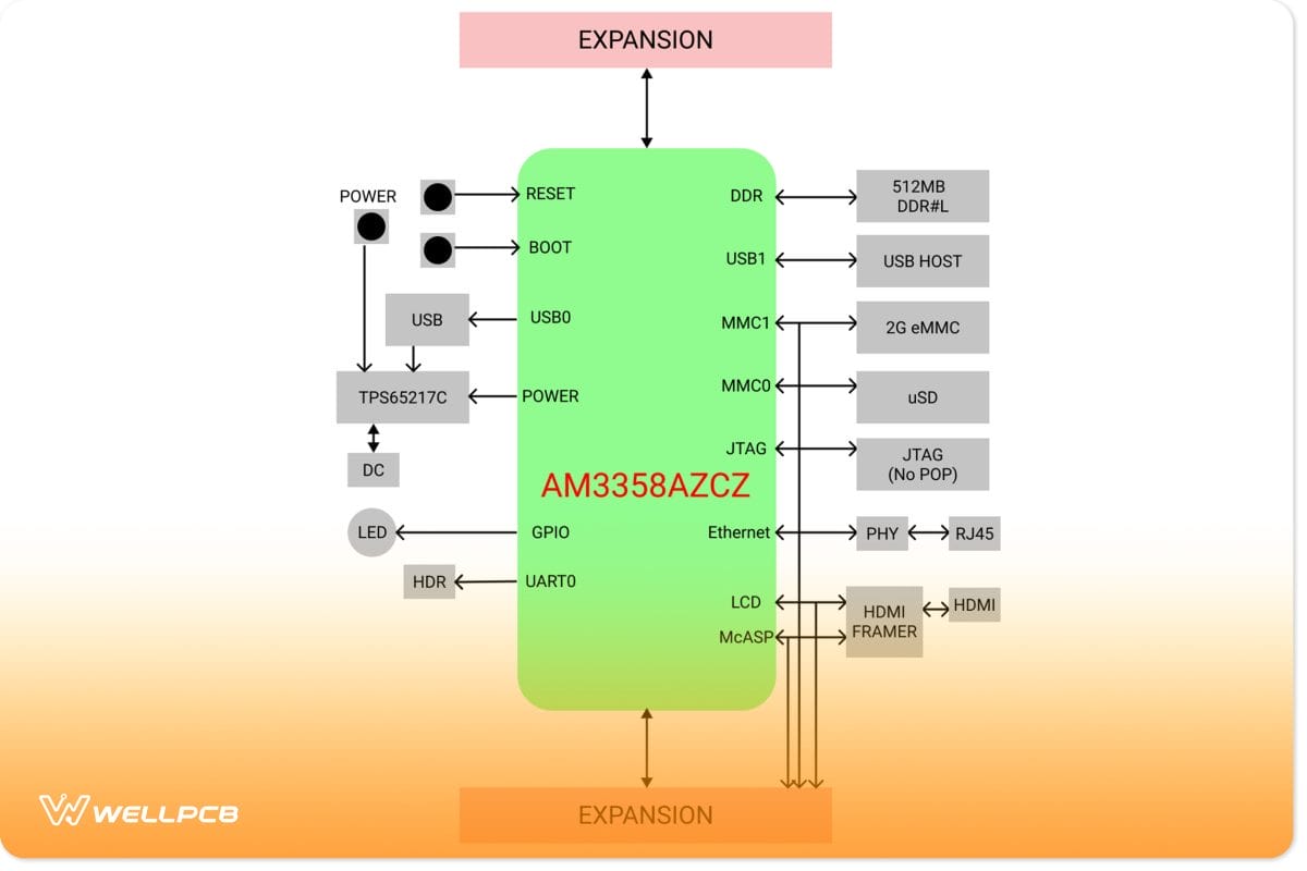
A2D chart of the Beaglebone black functionality
BeagleBone Black Application
- It is helpful for developers to test and create small network applications.
- Most IoT projects targeting commercial devices are also using the BeagleBone as a server.
- In some industrial equipment, the BeagleBone Black can subsequently become useful as a central control module.
- BeagleBone Black is also useful in applications that want to run heavy operating systems with low strength. Hence it is accessible and does serious operations with low energy.
- BeagleBone Black is indeed useful when you need your task to begin quickly.
- Beaglebone black LINX, in addition, takes very much less time to arise and stroll. It also comes with a pre-established LINUX distro, which saves quite a lot of time.
Summary
In summary, the Beaglebone open-source Linux-like approach has bridged the gap between industrial computers and session border controllers (SBCs). Consequently, beaglebone has facilitated increased exploration of artificial intelligence in many aspects of life. All while having pretty simple pre-installation tools. For more information on Beaglebone black LINX, feel free to contact us.