
You may be doing a project that requires you to know about blocking oscillators. Do you have worries that it might overwhelm you?
Blocking or pulse oscillator circuits are simple and exciting to work on yet have many applications in our day-to-day lives.
We appreciate the importance of blocking oscillators in electronic circuits and share our knowledge.
This article covers everything you need to know about them. Read on.
Contents
What Is A Blocking Oscillator?
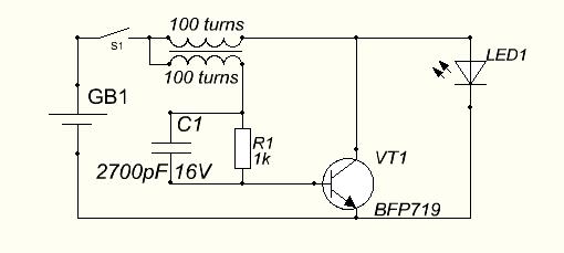
Fig 1: Blocking Oscillator Circuit Diagram
A blocking oscillator is a discrete wave generator employing a transformer, resistor, and amplifying element to produce a periodic pulse.
Some common amplifying elements are transistors and vacuum tubes.
It gets its blocking properties because its amplifying element undergoes blocking for most of its duty cycle.
Important parameters of the blocking oscillator are:
- Pulse repetition time
- Pulse width
- The Pulse repetition rate
Types of Blocking Oscillators
A pulse transformer is critical with all blocking oscillators since it generates a periodic pulse.
If the circuit produces a single pulse, it is a monostable circuit. And if the course can automatically change its state, it’s an astable oscillator circuit.
You must note that you cannot achieve a bistable operation using a blocking oscillator. This section below looks at the various classes of blocking oscillators.
Monostable Blocking Oscillator
A monostable blocking oscillator circuit comprises a three-winding pulse transformer and an emitter resistor. Blocking oscillators use load resistors or loads for damping purposes.
Furthermore, it uses the collector and base transformer turns to provide regenerative feedback. The third transformer leg is arbitrary and provides a negative or positive pulse across the load.
With that in mind, we have two types of monostable blocking oscillators.
- The Monostable blocking oscillator with base timing
- Monostable blocking oscillator with emitter timing
Monostable Blocking Oscillator With Base Timing
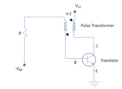
Fig 2: Schematic Of A Monostable Oscillator With A Base Timing
A monostable oscillator with a base timing pulse circuit consists of a pulse transformer, a transistor, and a resistor.
The pulse transformer provides feedback while the resistor controls the pulse duration.
It has a base to collector ratio of winding of n:1. Therefore, for every primary winding turn of the collector circuit, the base circuit has n secondary windings turns.
The transistor is initially OFF, and the base voltage, VBB, is too low. Therefore, you can assume VBB to be negligible. Thus, the transistor voltage is the VCC, the voltage across the collector circuit.
Introducing a negative input to the collector reduces the voltage across the collector, VCC. This results in an effective voltage increase at the transistor base.
The voltage increase at the base is possible due to the transformer’s winding polarities.
The circuit experiences sufficient voltage rise such that the voltage across the emitter and base, VBE, exceeds the cut-in voltage. Therefore, this induces a small current at the transistor.
Progressively, the small current causes a voltage drop across the collector while increasing the collector current. It also increases the loop gain. Eventually, it gets to a point when the transistor gets into saturation.
The above state is unstable, and the transistor achieves stability by getting into cut-off.
Monostable Blocking Oscillator With Emitter Timing
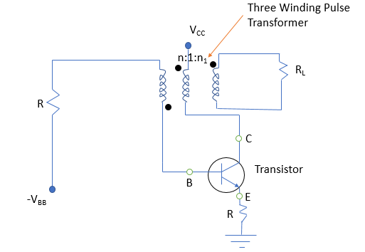
Fig 3: Schematic Of A Monostable Oscillator With An Emitter Timing
An emitter-timed monostable oscillator has a circuit pulse width insensitive to the current gain. Its emitter circuit has a timing resistor to control the pulse width.
You must use a three-winding pulse transformer with the collector and the base.
The primary windings connect to the collector, while the secondary windings connect to the base. Connect the third winding to a load resistance for damping purposes.
This arrangement facilitates power polarity inversion across the transformer primary and secondary windings.
For the emitter-timed oscillator, the emitter resistance controls the output pulse period.
Astable Blocking Oscillators
We have two types of astable blocking oscillators.
- Diode controlled astable blocking oscillators
- RC controlled astable blocking oscillators
Diode Controlled Astable Blocking Oscillator

Fig 4: Schematic Of A Diode Controlled Astable Blocking Oscillator
The above blocking oscillator has a capacitor between its transistor’s base and the transformer’s secondary. You use a diode to connect the collector of the transistor and across the transformer primary winding.
The astable blocking oscillators’ operation relies on introducing an initial pulse at the collector, after which you remove the pulse. In this state, the diode is reverse biased. Therefore, any voltage at the transformer terminals will induce at the base without phase change.
Eventually, the base current rises, and the transistor develops a base-to-emitter voltage, VBE. A sufficient VBE overcomes the cut-in voltage and turns on the transistor.
The build-up in collector current forward biases the diode and reflects at the transformer winding, charging the capacitor. The charging capacitor is OFF since it won’t discharge current while charging. The recent base drops sufficiently to turn the transistor OFF.
Therefore, the voltage across the diode sets up at the transformer primary and across its secondary. Hence, the capacitor discharges, and the base current turns the transistor ON, and the process repeats itself.
RC Controlled Astable Blocking Oscillator

Fig 5: Schematic Of A RC Controlled Astable Blocking Oscillator
Add a timing resistor and capacitor circuit to the emitter in the RC-controlled blocking oscillators. Their role is to control the pulse timings of the oscillator.
The principle of operation is much similar to the diode-controlled astable blocking oscillators. The capacitor discharge isn’t under the diode’s control but by a time constant set by the resistor-capacitor network.

How A Blocking Oscillator Works
An oscillator relies on the pulse transformer to generate a rectangular waveform and a resistor to control the output frequency.
In a dormant state, the transistor’s base voltage is minimal, and hence it is in an OFF state. Base voltage shouldn’t be zero to avoid false noise triggering of the oscillator.
Applying a pulse signal to the collector lowers its potential and raises base potential due to transformer action.
Eventually, a stage reaches when the voltage across the base and emitter, VBE, exceeds the knee voltage. The transistor is out of the cut-off phase causing the collector current to decrease. And as a result of the phase inversion by transformer action, the base potential rises.
If the base potential rises and the transistor gains more than once, it’s driven to saturation. The collector current rises during the saturation period while the collector voltage remains constant.
The emitter current is determined by the emitter resistor and the transformer feedback. A rise in collector current causes a constant decrease in the base current.
Eventually, a point reaches when the base current is sufficiently low to push the transistor to cut-off. The cycle or pulse then repeats itself.
Blocking Oscillator Applications
- They’re critical as periodic switches in electronic circuits
- Blocking oscillators can also be used as frequency dividers in digital circuits
- They’re also key for generating large peak power pulses
- They’re critical as switches in low impedance systems
Conclusion
In conclusion, we’ve discussed the critical aspects of blocking oscillators and how you may apply the knowledge in real life.
If you need help with blocking oscillators or your project, feel free to reach us at any time.


