Contents
- 1 What is the Brushless Motor?
- 2 The Characteristics and Specification of a Brushless DC
- 3 A Brushless Motor Pin Configuration
- 4 Brushless Motor Controller Schematic
- 5 Where to use the Motors
- 6 How to Complete Brushless Motor Wiring
- 7 Brushless motor wiring: Why Does a BlDC Controller Have Three Wires?
- 8 Summary
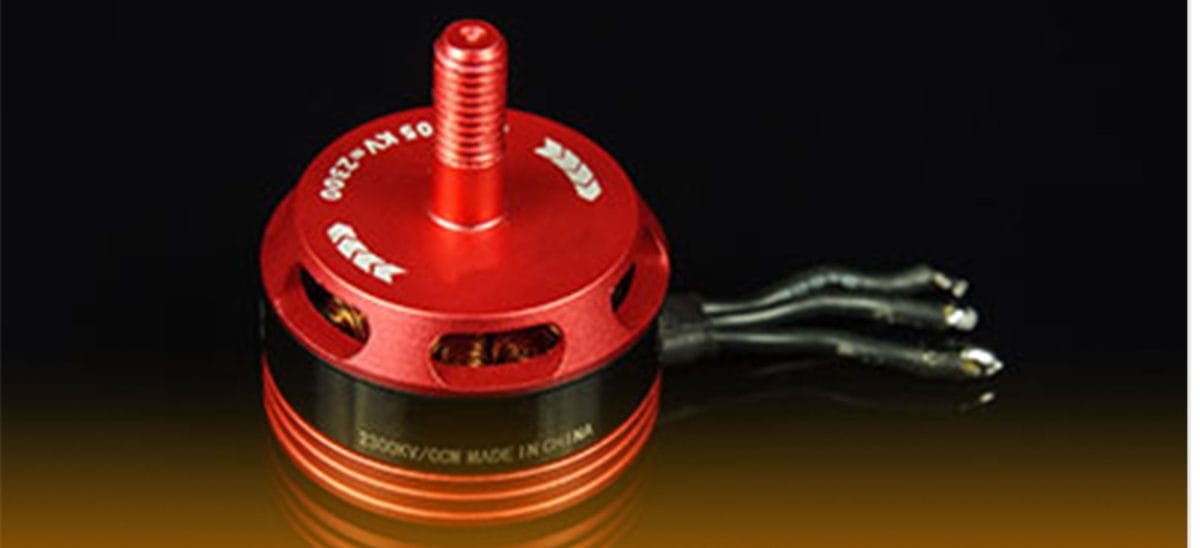
What is the Brushless Motor?
A DC motor is an electric motor made explicitly for electric equipment that can propel. There are two types of these motors: the in-runner and the outrunner. The in-runner has the runner’s inside rotating while the outside remains fixed. At the same time, the outrunner type has the inside of the motor fixated while the outside is spinning.
A brushless DC motor works similarly to the brushed DC motor. However, the only difference is that the brushless motor spins faster, last longer, and helps save battery energy.
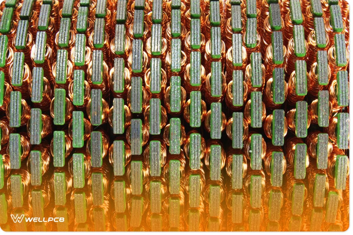
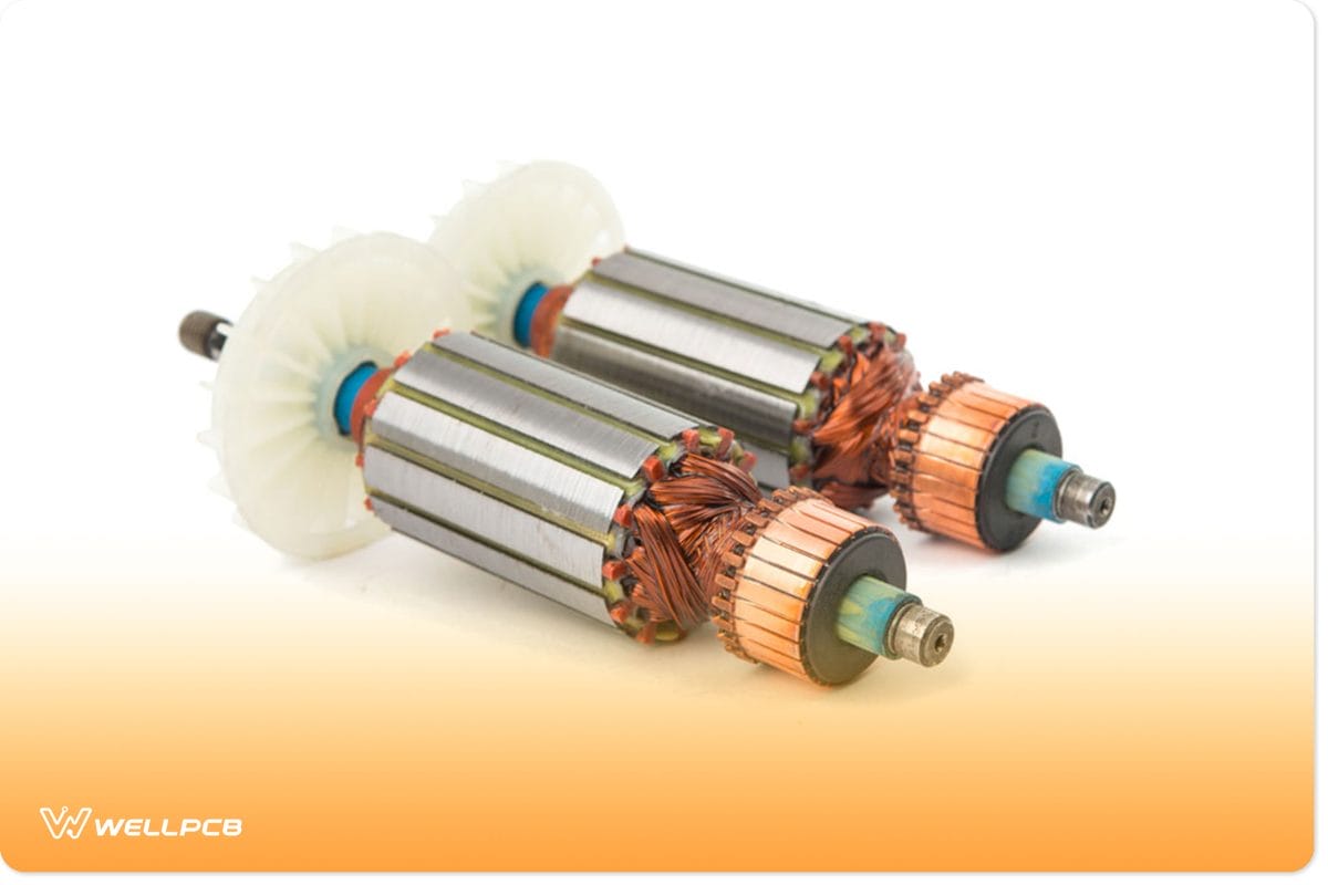
(parts of a disassembled BLDC motor.)
The Characteristics and Specification of a Brushless DC
- First, it carries a maximum current of 13A for 1 minute.
- Secondly, it can operate under a maximum temperature of up to 80⁰C
- Also, the motor weights around 50-60g
- Moreover, it can carry a maximum power of 150watts
- Additionally, it has an operating voltage of 10v, more or less
- And, it has a three-phase connection that helps regulate the motor’s speed.
- Lastly, it has a load current of 0.5A.
However, there are no specific industrial standards, as these are vital characteristics to look for when buying a brushless motor. Since several industries manufacture brushless motors with different ratings, this is the cause of existing variable features.
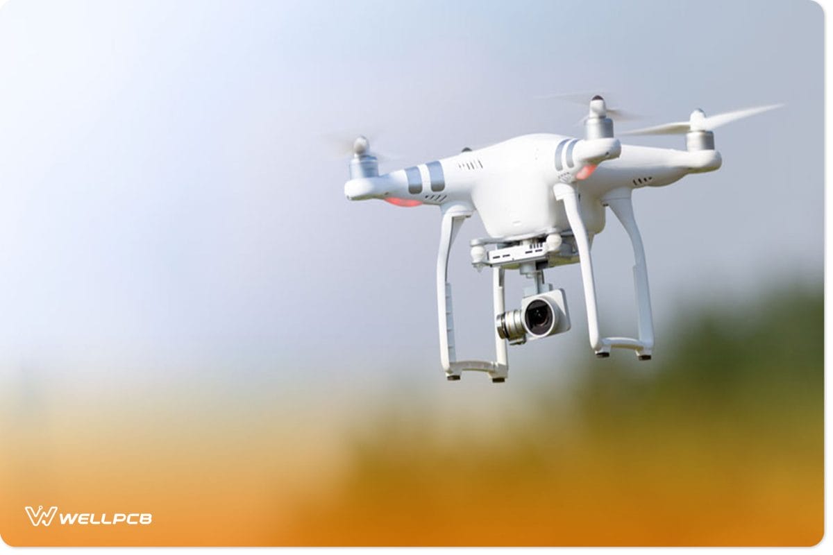
(an electronic device that uses the engine.)
A Brushless Motor Pin Configuration
We already know that a brushless motor is a three-phase motor. Below is a table that describes each pin configuration.
| Pin name | Description |
| A | connects to phase 1 |
| B | connects to phase 2 |
| C | connects to phase 3 |
Brushless Motor Controller Schematic
In this motor, the rotator carries a bunch of permanent magnets and then spins them in the direction of the magnetic field. When this spin is happening, the coil is constant and not affected by the magnetic field.
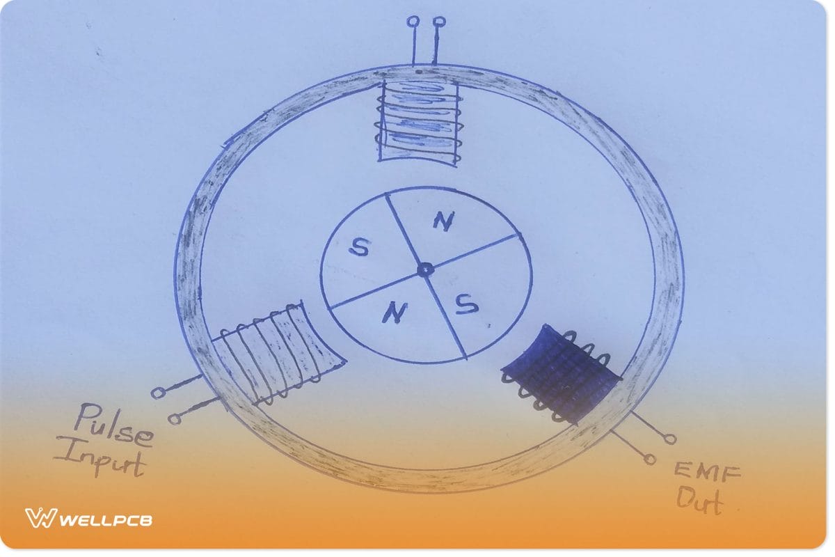
(brushless motor controller schematic diagram)
Since the magnets are now in motion and operating without the terminals, they can easily spin. The magnets’ rotation is often at high speed and primarily noiseless.
However, the magnet pairs need to shift constantly for a magnetic material to react to the permanent magnetic field. Moreover, this spin happens so that the two poles can regularly respond and experience an opposing force. Consequently, the energy produced will release a tensional pressure over the rotor and initiate the resultant force.
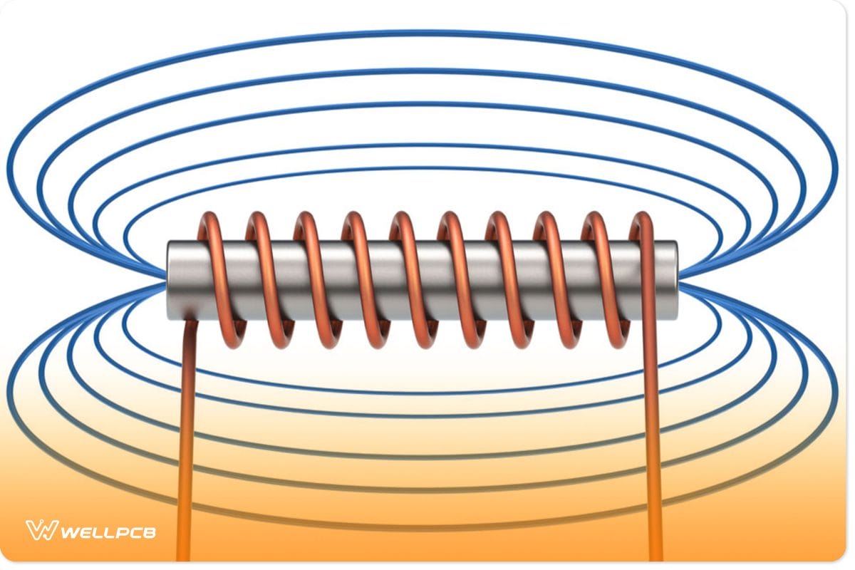
(an electromagnetic field.)
Where to use the Motors
We primarily use the BLDC controller where the project requires a low cost to bring it to life. Since it is an inexpensive and readily available motor, this is why it’s highly preferred.
We can accurately control the motor’s speed because of the presence of the 3-phase controller.
Moreover, we use this motor with many driver modules since they are easy to operate. With these driver modules, we can easily regulate the engine’s speed.
How to Complete Brushless Motor Wiring
A BLDC electronic speed controller is not like a typical DC motor. So, we cannot connect it directly to the supply voltage and expect it to work.
We need to follow a unique powering pattern to run the three-phase motor. Notably, there are six complete steps to follow to achieve this;
| Step | 1 | 2 | 3 | 4 | 5 | 6 |
| Positive | A | A | B | B | C | C |
| ground | B | C | C | A | A | B |
| open | C | B | A | C | B | A |
The steps shown below indicate rotation in the forward direction. When we need a reverse process, we should follow the steps in reverse.
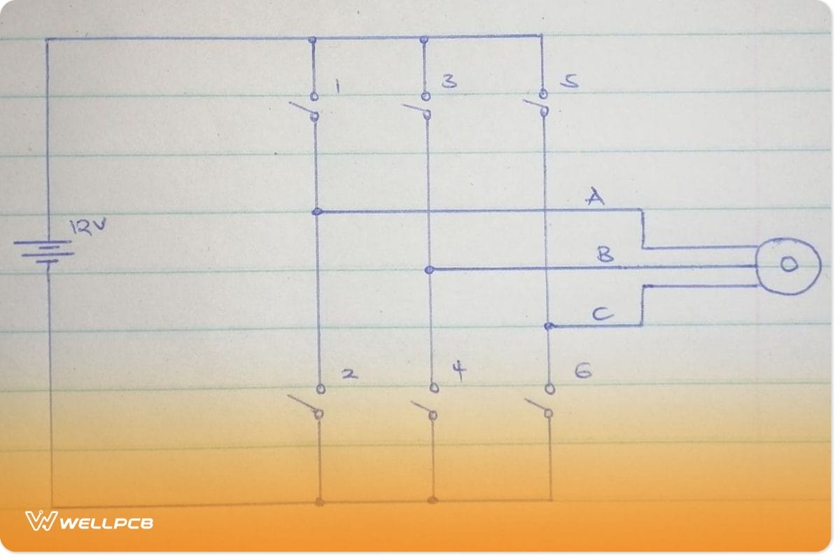
(a BLDC motor circuit with switches in an h-bridge form.)
To understand the table above, we should consider the circuit above. Windings 1,2,3,4,5,6 are called phase windings.
- In step 1, we close switches 1 and 4. Winding 1 and 2 were found inside the motor power hence completing the step.
- In step 2, we close switches 1 and 6. Winding 1 and 3, then power completing the step.
- In step 3, switches 3 and 6 close, making the winding of 2 and 3 energize therefore completing the step.
- In step 4, switches 3 and 2 close, winding 2 and 1 inside the motor to energize. Consequently, it completes the step.
- In step 5, switch 5 and 4 close, winding 3 and 1 to power up, completing the step.
- In step 6, switch 5 and 4 close. Winding of 2 and 3 energizes, therefore completing the step.
In a reverse rotation, this process is entirely reversed. Sometimes, this process can cause many problems since some people consider it complex. We advise you to use an electronic speed control called the driver modules if you find it problematic.
(an electric motor with coil windings.)
Brushless motor wiring: Why Does a BlDC Controller Have Three Wires?
Three wires in this motor are necessary because the motor driver requires a complex circuit. The BLDC circuit controls the power signals needed in the rotation process.
Also, the three wires ensure its efficiency, making it the best choice for motors in airplane applications.
Summary
The BLDC motor is highly efficient in drones and planes. BLDC motors are readily available and should be carefully chosen since they have different speeds. You should correctly read and understand the datasheet before purchasing or using it.
We hope this article is of great help to you. Would you please reach out to us for more information on this article or any circuits?