Contents
What is a Capacitive Voltage Divider?
A capacitive voltage divider is a circuit that takes a potential voltage difference and splits it into two while maintaining a constant voltage ratio.
In addition, a capacitive divider will generally have a pair of capacitors in line with each other.
The primary purpose of this circuit is to allocate various quantities of voltages to other circuit parts following Ohm’s law:
V=IR
Where V represents voltage, I means current, and R is resistance.
For instance, when you have a 12-volt power supply, you place four capacitors in series with each other (and all of them are 1µF).
Then, the capacitors will offer a voltage output of 6 volts, which is half the 12 volts.
What is a Voltage Divider Rule?
On average, the input voltage splits through the elements when a couple of circuit elements are interlinked in series.
Similarly, when you interlink some circuit elements parallel, the current will also split throughout the components.
Consequently, we use the current divider rule for parallel circuits, and for a series circuit, we employ the voltage divider rule when analyzing the course.
The voltage divider rule, another name potential divider rule, plays a critical role in circuit analysis as it helps us calculate the individual voltage of the elements.
The voltage divider rule will fall into three categories depending on the elements used in a circuit.
Namely;
- Inductive voltage divider
- Capacitive voltage divider
- Resistive voltage divider
Let us have a closer look at each of the above.
Voltage Divider Rule for Resistive Circuits
To comprehend the resistive voltage divider rule, let us use a circuit with a pair of resistors linked in series to the voltage source.
Since you interlinked the resistors in series, they (resistors) both have a similar amount of current flowing through them.
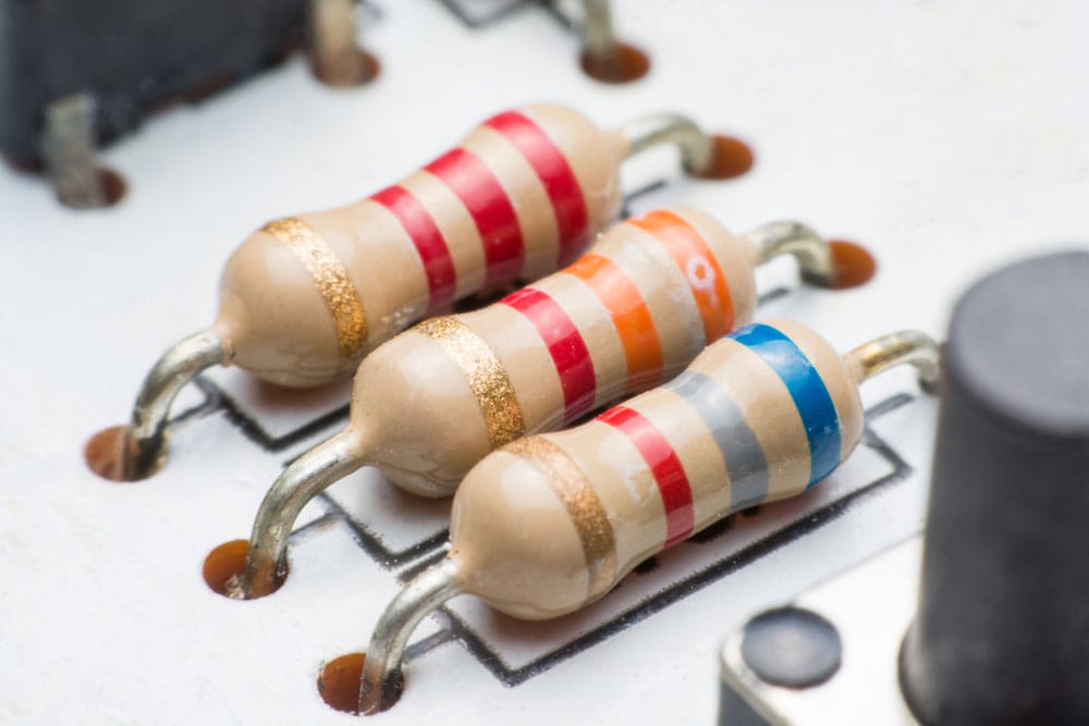
Resistors
However, the resistors have a contrasting voltage; the circuit’s input voltage splits into the pair of resistors.
In addition, the resistance directly affects the quantity of individual voltage.
Below is a circuit you can use for further understanding:

A resistive circuit
From the circuit diagram above, the resistors R1 and R2 interlink in series with VS (the voltage source). The voltage source provides a 1-ampere total current.
Nevertheless, the designer affixed all the elements in series; consequently, there will be a loop, and the current moving through them will remain constant at 1 ampere.
Now, to calculate the sum voltage, you can use the formula;
VS = VR1 + VR2 … (1)
Where,
VR1 represents the voltage through Resistor R1, and VR2 represents the voltage through resistor R2. Moreover, all the provided voltage splits between these two resistors. Thus, you can get the sum voltage by adding VR1 and VR2.
Following OHM law:
VR1= IR1+IR2…. (2)
Thus, from equations (1) and (2),
VS= IR1+IR2
VS= I(R1+R2)
Next, place the value from the first current in equation (2)
VR1 = IR1

Likewise
VR2 = IR2

Thus, a resistive circuit’s voltage divider rule contradicts the current divider rule.
Voltage divider rule for Inductive circuits
When you interlink three or more inductors in a circuit in series mode, the current flowing through the inductors remains constant. Nevertheless, the source voltage spreads to all the inductors.
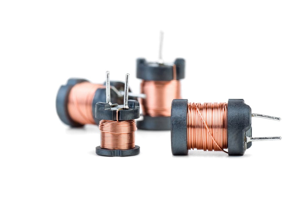
Inductors
Therefore, you can use the inductor voltage divider rule to calculate the amount of voltage in an individual inductor.

An Inductive circuit
The designer linked both inductors L1 and L2 in series mode from the above circuit diagram. In addition, VL1 represents voltage through L1, and likewise, VL2 represents voltage through L2. The VS shows the supply voltage.
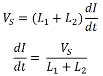
To find VL1 and VL2, we use the inductor voltage divider rule. As you already know, the equation for inductor voltage is;

Where Leq equals the circuit’s sum inductance, the electrical engineer interlinked the inductors in series in our example circuit. Thus, the sum inductance is a combination of the two inductances;
Leq = L1+ L2
From equation (3);
Voltage through inductor L1 is;

Likewise, voltage through inductor L2 is;

Thus, we can conclude that an inductor’s voltage divider rule is similar to the resistors.
Voltage divider rule for Capacitive Circuits
Let us use the circuit below to calculate a capacitor’s voltage divider rule.
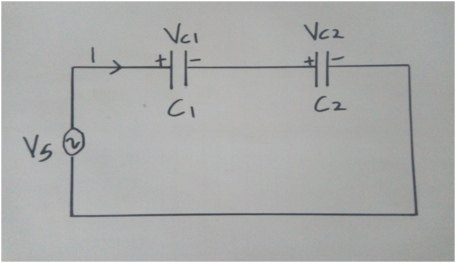
A Capacitive circuit
Where;
The engineer affixed a pair of capacitors in series with VS, the source voltage. Next, the source voltage splits into two. One goes through capacitor C1 and the other through capacitor C2.

Capacitors
In addition, VC1 represents voltage through capacitor C1, and VC2 stands for voltage through capacitor C2.
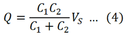
Thus, the combined capacitance is

The sum charge provided by the source: Q = Ceq VS, which is essentially
Capacitor C1 voltage;
VC1 = Q1/ C1

Capacitor C2 voltage;
VC2 = Q2 / C2

In summary, individual voltage through a capacitor is a ratio of opposite capacitance multiplied by total capacitance and total voltage.
Capacitive Voltage Divider Formula
A capacitive voltage divider is a circuit that uses a pair of capacitors parallel to the output and interlinked to the AC (Alternating current) input.
You can get the ratio of the input and output voltage using the formula;
Vout/Vin = 1/ (1+CS/CP)
Where;
- CS represents the entire capacitance of the whole series-connected capacitors.
- CP represents the sum capacitance of every parallel-connected capacitor.
The above formula supplies an Alternating current (AC) signal with a magnitude that depends on the Vin with an offset.
However, the offset varies regarding the amount of capacitance of CS or CP.
Circuit Diagram of Capacitive Voltage Divider
Capacitive AC Voltage Divider Circuit
The formula XC= 1/ (2πfc) guides voltage division through individual capacitors in a capacitive voltage divider circuit.
Even so, to calculate the amount of voltage allocated to the circuit’s capacitors, you need first to calculate the capacitor’s impedance. You can do so using the above-stated formula.
After calculating the impedance, you can then employ the OHMs formula to know the amount of voltage passing across each capacitor.
For instance:

A capacitive AC voltage divider circuit
The above circuit has two capacitors and a 120V AC supply voltage; consequently, the voltage will flow to both capacitors. Remember that the capacitors are in series mode.

You can now employ a simple voltage divider to know the allocated voltage, where the 1μF capacitor will get twice the voltage.
Hence, in our case, it will be 80V, and capacitor 2μ will get 40V
Capacitive DC Voltage Divider Circuit
The voltage is shared in a DC Voltage divider circuit regarding the formula V=Q/C.Whereby the voltage is oppositely symmetrical to the capacitor’s capacitance value.
In essence, the capacitor having a lower capacitance will receive a higher voltage. On the other hand, the capacitor with more capacitance will receive a lesser voltage.
For instance:
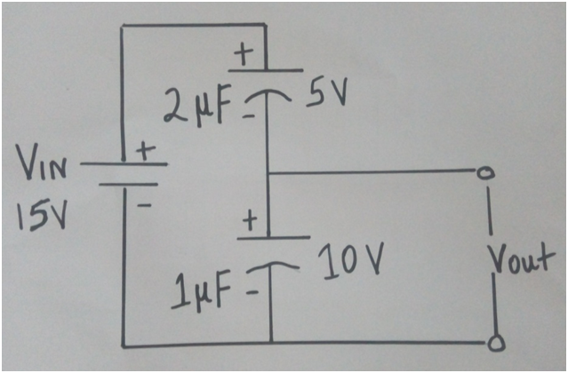
Capacitive DC Voltage Divider Circuit
The above circuits supply a DC voltage of 15V, which means that the 15 volts will flow through to the pair of capacitors.
The voltage will flow to both capacitors so that when totaled, it will equal the supply source 15V.
Presuming the capacitors have a similar charge, you can calculate the voltage from their capacitance values.
Given that the 1μF capacitor value is half the 2µF capacitor value, the voltage of the first capacitor will be twice that of the second.
Hence, the 1μF capacitor voltage will be 10 volts, and the 2µF capacitor voltage will be 5 volts.
Advantages and Disadvantages of Capacitive Voltage Divider
Voltage dividers are helpful, but they, too, have pros and cons like all other inventions.
Advantages
- Minimal heat loss
- Affordable
- Work on either DC( Direct current) or AC (Alternating current)
- Low installation cost
- Frequency-dependent
Disadvantages
- works solely on Lightweight AC
- Fairly heavy
- Overheating lowers working efficiency
- A few voltage dividers are costly to install, and they will only work with AC.
Uses of Capacitive Voltage Divider
As mentioned earlier, capacitive voltage dividers have numerous applications. Some of them include:
- A voltage divider can lower the voltage and enable measuring of high-level voltage.
- Voltage dividers inside a microcontroller aid the measurement of a sensor’s resistance.
A microcontroller
- A voltage divider works as a logic level shifter when interfacing with various operating voltages.
Summary
After reading this article, we hope to define a capacitive circuit and explain the voltage divider rule.
Understanding a capacitive voltage divider’s various advantages and disadvantages would be best.
If you require further information on the subject, don’t hesitate to get in touch with us.


