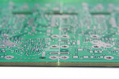
Capacitors are important devices necessary for most electronic applications. Plus, they can store electrical energy making them powerful devices. However, it doesn’t come without faults. Capacitors can suffer from leakage current which is the result of imperfections in the oxide layer. Plus, capacitors with leakage current can become a big problem in your circuits. Luckily, there’s an easy solution to this problem. All you need is a capacitor leakage tester!
Though capacitors have a variety of tests, the leakage test is one of the important tests.
So, in this article, we will tell you everything you need to know about the capacitor leakage tester and how to build a simple and affordable leakage tester circuit.
Are you ready? Let’s learn!
Contents
DIY Capacitor Leakage Tester
As mentioned earlier, capacitors have various tests to check if they work properly. For this reason, there are different capacitor testers. You might even have some of these testers in your kit.
However, these capacitor testers are not leakage testers. They don’t measure the current that flows through a capacitor at its set rated voltage. Plus, we know that capacitors start leaking as they age. So, here’s an easy DIY capacitor leakage tester to help you check when you have leaky capacitors.
But, there’s a catch.
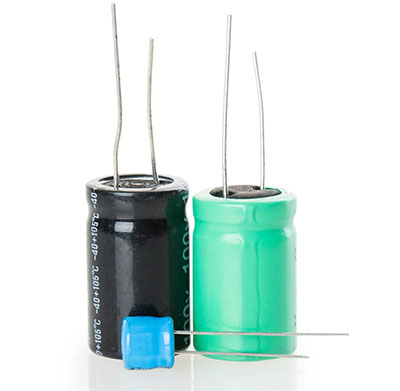
This leakage tester can’t handle high voltage. In other words, you won’t get enough current to test 1 mfd capacitors or higher. So, it might not give you the best results when testing electrolytic capacitors. However, if you have capacitors below this value, this tester will get the job done.
Note: If you want to test electrolytic capacitors, then try measuring the equivalent series resistance (ESR).

How the Circuit Works
This easy DIY leakage tester circuit works with an Astable multivibrator using two 2N3904 transistors that runs at about 10 kHz. We picked this frequency because the miniature transformer (10-1 ratio) was most efficient at this frequency.
Also, we get a coupled signal from the second transistor through a 15 nF capacitor—to the gate of an IRF630 MOSFET. This MOSFET gate is biased at 4.5 volts between the two megohm resistors.
Plus, one of these megohm resistors is a variable resistor that varies the size of the signal moving into the gate. Thus, varying the output voltage.
Additionally, the drain of the IRF630 steps up from 25 volts peak to about 225 volts peak—when you connect it to the primary of a step-up transformer (1-10 ratio). Next, it applies this stepped-up voltage to a voltage multiplayer. Thus, the final product is about 1000 volts of DC.
To finish the process, the circuit applies 1000 volts of direct current to two external terminals. Also, the positive side goes through a 0-400 microamp meter movement to the positive terminal. Finally, the external terminals are banana terminals so that you can fit various standard-sized meter probes. This circuit gets a supply of 9v battery current through the push button switch.
Components and Tools Needed
Here are the parts and tools you need to build this circuit:
- Electronic solder
- Assorted screwdrivers
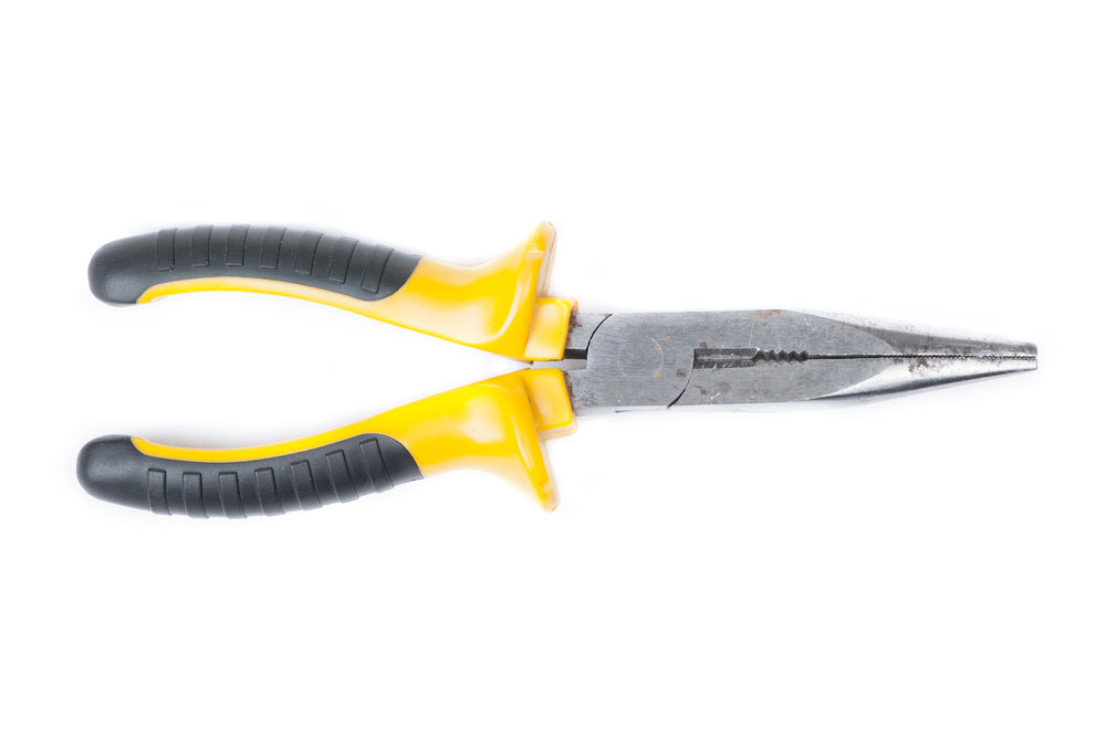
- Long-nosed pliers
- 40 watts soldering iron
- Reamer and miniature file set
- Electric drill with drill index
- 2N3904 bipolar transistors (2)
- 15 nF capacitors (3)
- IRF630 MOSFET (1)
- 4.7k resistors (2)
- 1N914 diodes (2)
- 1k resistor (1)
- ½ watt, 1 megohm potentiometer (1)
- 10-1 miniature audio transformer (1)
- 9-volt battery connector (1)
- 9-volt battery (1)

- 2000 pF capacitors rated at least 400 volts (13)
- 1N4007 diodes (13)

- Set of banana jacks, one red one black (1)
- Miniature analog meter for current indication. Preferably less than a 1 milliamp movement (1)
- Different colors of hookup wire and heat shrink tubing to fit over wires that carry high voltage
- Knob for potentiometer
- Miniature push-button switch (1)
Steps
Here are the steps to follow when attempting this circuit:
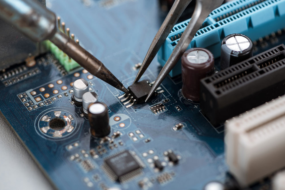
Step 1: Assemble and Install Components
First, a box and drill the necessary holes for the push button switch, meter, potentiometer, and two holes for the banana plugs. Next, install the components on the top and bottom halves of the box using the right-sized drill bits.
Step 2: Make your Crocroft-Walton Voltage Multiplier
Use a piece of Veroboard to make your voltage multiplier. Use one that’s 3 by 1 ½ inches so the components can fit neatly.
Step 3: Make Your Multi-vibrator
Use a piece of 3 by 1 ¾ inches Veroboard to build a multivibrator. Once you’ve done with the multi-vibrator, make sure it operates at 10 kHz.
Step 4: Wiring
Next, ensure you wire everything together. Wire the high voltage wires with a regular hook-up wire—featuring a sleeve of heat shrink tubing on the body of the wire.
Step 4: Test Your Circuit
Use your tester to check out those bad capacitors in your kit. Ensure it works properly in case you have to re-wire all the components.
How to Test this Circuit
After assembling the parts, test first with scope. So, check out the signal from the gate of the far left MOSFET, you should see a positive 9 volts sawtooth waveform. This sawtooth waveform should have approximately 1 microsecond of negative spike due to the capacitance input of the MOSFET.
Also, the second waveform should show when the MOSFET drains after connecting to the transformer. Plus, you should notice the more rounded off waveform until it reaches the 20 volts peak.
Note: the first spike of 25 volts at the beginning of the waveform was due to the primary transformer’s resistance to the change of current it receives.
Now, the third waveform shows the signal when it moves out from the transformers and applies to the voltage multiplier input. The peak here is approximately 225 volts. Thus, the voltage multiplier will multiply this voltage to about 1000 volts DC.
That’s not all.
Once you’re done with scope testing, use the leakage tester to check some capacitors. For our test, we used a modern capacitor with a 400 volts rating and an old-fashioned paper capacitor with the same 400 volts rating.
For the modern capacitor, we used the leakage tester to apply approximately 400 volts and the leakage was around 25 microamps. That’s a small leakage so the modern capacitor passed the test.
On the other hand, we applied the same 400 volts to the old-fashioned capacitor and we found it passing through 10x the current. That’s a big leak, thus making it unfit for any circuit.
Final Words
A simple capacitor leakage tester can test leaky electrolytic capacitors within the range of 1uf to 450uf. Also, it’s capable of testing large start and run capacitors and smaller 1uf capacitors with 10v ratings.
However, once you grasp the timing cycle, you could test below 1uf (0. uf) and higher than 450uf (up to 650uf). What’s more, you can also use this tester to check insulation resistance in wires and test the reverse breakdown characteristics of a diode.
Note: Be careful! This device is capable of developing high voltages up to 1000 volts. Misusing this device can be lethal. So, proceed only if you understand the safety measures for working with high voltages.
Well, that wraps up everything you need to know about the capacitance leakage tester and how to make one. If you have further questions, feel free to contact us and we’ll be happy to help.