Contents
- 1 Carbon Film Resistor VS Metal Film: Definition
- 2 Carbon Film Resistor vs Metal Film Resistor: Side-by-Side Comparison
- 3 Carbon Film Resistor VS Metal Film: Construction
- 4 Carbon Film Resistor VS Metal Film: Availability
- 5 Carbon Film Resistor VS Metal Film: Similarities and Differences
- 6 Carbon Film Resistor VS Metal Film: Drawbacks
- 7 Conclusion
Carbon Film Resistor VS Metal Film: Definition
A carbon film resistor is a type of resistor that slows the flow of electricity by using a thin layer of carbon. Unfortunately, carbon film resistors are more expensive to make than other types of thin film resistors. They also generate a lot of thermal noise and can portray low accuracy.

(carbon film resistor)
Despite its challenges, it can withstand high-energy pulses and thus are suitable for applications like surge protection electronic circuits, computers, test equipment, DC power supplies, and high-frequency applications.
A metal film resistor limits the flow of electricity by using a thin metal film. It is also the most popular type of thin film resistor. Moreover, metal resistors are cost-effective, compact, have low tolerance, generate less noise, and operate widely compared to carbon resistors.

(metal film resistors)
Therefore, you’ll find them in bridge circuits, active filters, and high-frequency applications.
Carbon Film Resistor vs Metal Film Resistor: Side-by-Side Comparison
Now that we’ve defined these resistor types individually, let’s look at a head-to-head comparison of them both. This will make it easier to know which use cases would suit each resistor type best. The properties this section will focus on are the voltage coefficient of resistance, stability, and temperature coefficient of resistance.
Temperature Coefficient of Resistance (TCR)
Similar to how the amount of voltage applied to a resistor can affect its resistance, changes in temperature have an effect, too.
Of course, this phenomenon isn’t exclusive to resistors. All conductors have resistance of some sort which increases in high temperatures and decreases in low temperatures.
We express this value as parts per million per degree Centigrade (ppm/°C) or Kelvin (ppm/K). As with the previous property the resistance value of metal film resistors is less susceptible to change in temperature than carbon film resistors.
Metal film resistors have a TCR between ± 20 and ± 200 ppm/k. On the other hand, carbon film resistors have a TCR between -200 to -1000 ppm/k.
As such, the carbon film resistor TCR is substantially greater than the metal film resistors. This makes metal film resistors more reliable under extreme temperatures (both hot and cold).
Moreover, metal film resistors produce less thermal noise. This makes them ideal for devices such as radios, intercoms and radars.

Carbon Film Resistor Green Color
Voltage Coefficient of Resistance (VCR)
Applying voltage to a resistor may cause changes in its resistance value. Usually, applying voltage to a resistor causes the resistance to drop in near proportionality.
Regardless of decrease or increase, we represent the change in resistance against each applied volt (per volt).
This measurement is known as the Voltage Coefficient of Resistance (VCR) and is represented by the metric: parts per million per volt (ppm/V).
The VCR is important because it helps us predict and determine how well a resistor performs in high-voltage situations. While carbon film resistors perform well in high-voltage applications, their metal film counterparts perform even better. Metal film resistors have a VCR of just under 1 ppm/V, whereas carbon film resistors have a -10 ppm/V. This means metal film resistors are less susceptible to changes in resistance caused by applied voltage.
Stability
Since resistors are a part of machinery and electronics operating in various environments, we must know how they are fair against external stressors. These stressors can (potentially) affect the resistance value of the resistor. We refer to a resistor’s tolerance to environmental stressors over time as stability.
Some of the most common stressors are exposure to radiation, heat (high temperatures), and cold (low temperatures). Sudden or prolonged power spikes can also be categorized as stressors that can challenge the stability of the resistor.
Nevertheless, stability is another area in which metal-film resistors outperform carbon-film resistors. This is not to say that carbon-film resistors are unstable. They have moderate stability. On the other hand, metal film resistors exhibit good to exceptional stability.
Carbon Film Resistor VS Metal Film: Construction
The two resistor types have different processes.
Carbon film resistor construction
Manufacturers make carbon composition resistors from a solid, cylinder-shaped resistive element with wire leads and metal caps on the ends. Further on, the materials in the resistive element are a mixture of clay-based ceramic and graphite or carbon powder. Generally, the carbon powder lets electricity flow through it well.

(Internal part of a carbon film resistor)
So, during the deposition process, manufacturers start by heating the ceramic substrate in a hydrocarbon like methane. Next, at high temperatures of approximately 1000°C, cracking reactions will occur in the gas. The pure graphite’s crystalline carbon then sticks to the ceramic.
Afterward, the resistive material gets a plastic covering to keep it safe from the heat generated from outside. Manufacturers finally apply copper to make the wire leads at both ends of the resistive element.
Metal film resistor construction
Contrarily, manufacturers use a special method for metal film resistors, where they artificially age the deposited metal in low temperatures for an extended time.
Here, the material employed as the resistance material is Nickel chromium (NiCr). However, in other applications, you’ll find other materials like tantalum nitride, gold with platinum, and tin plus antimony.
Then, the resistor’s stability and resistance often depend on the metal film thickness. Thus, a larger thickness will mean a lower resistance value and greater stability on both films ends.
Manufacturers use connection leads to press a metal cover for the final touches. They can now achieve the desired resistance via a spiral-shaped slot cut in the thin metal thickness.
Carbon Film Resistor VS Metal Film: Availability
Carbon Film Resistor
You’ll find carbon resistors in 1 ohm to 25megaohms with a power rating ranging between one-quarter watt and five watts.
The three factors affecting the resistance of carbon film resistors are;
- The solid cylindrical rod’s cross-sectional area is inversely proportional to the resistance of the resistor.
- Then, we have the rod’s length directly proportional to the resistance.
- Lastly, the amount of carbon you add to the resistor is inversely proportional to the resistor’s resistance.
Metal Film
Usually, the available metal film resistors in the market have tolerances of 2%, 1%, 0.5%, 0.25%, and 0.1%. Additionally, the resistors are likely to have temperature coefficients ranging from 10 to 100 ppm/K and some resistance.
The two main factors affecting the resistance of metal film resistors include:
- The width of the spiral metal film cut is inversely proportional to the metal film resistor resistance.
- Secondly, the layer of the metal film is also inversely proportional to the resistance.
Carbon Film Resistor VS Metal Film: Similarities and Differences
- Similarities
The film resistors are similar in the following ways;
- First, you can regulate both by controlling their thin film thickness.
- Then, their non-conducting material is ceramic.
- They also have the same size.
- Lastly, their shape and appearance are similar.

(Film resistors in a circuit board)
- Differences
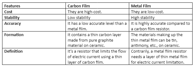
We have summarized the differences between the metal film and carbon film resistors in the table below.
Carbon Film Resistor VS Metal Film: Drawbacks
Both these resistor types have advantages. While metal film resistors have the best frequency response of all resistors, carbon film resistors are more affordable and have high resistance. However, both these resistor types have drawbacks and limitations.
For instance, as we previously discussed, one of the biggest disadvantages of using carbon film resistors is their high-temperature coefficient of resistance. In addition to this drawback, they also have comparatively subpar stability, especially when compared against wire-wound and metal-film resistors.
Another somewhat cumbersome feature of carbon-film resistors is their bulkiness.
As a consequence of their larger size, they can be a little difficult to maneuver and place, especially by hand. Contrastingly, metal-film resistors are compact, which makes them ideal for smaller electronics.
While, in many ways, metal-film resistors may be superior to carbon-film and carbon-composite resistors, they aren’t without their own drawbacks.
For one, they’re generally more pricier than carbon film resistors. Moreover, they have higher power dissipation.
Some may see this as an advantage, but it’s an attribute that makes them unsuitable for use cases that require low-power dissipation resistors.

Metal Film Resistor On Green Blur
Conclusion
Both carbon film and metal film resistors limit current flow through circuits. However, carbon film resistors use carbon, while metal film resistors use metal to reduce current flow.
For more information on the resistors, kindly reach out to us.