
Oscillators are some of the most incredible gadgets used in modern-day electronic circuits. Consequently, we’ll look at the Clapp oscillator, which is one of the most well-known basic oscillators around. In the case of material curiosity of the Clapp oscillator, I recommend first to learn the theoretical fundamentals as we will discuss in this article. Afterward, you can acquire the Clapp oscillator to make more practical applications.
Contents
1. What is a Clapp Oscillator?
Clapp oscillator, also known as Gouriet oscillator, is an electronic oscillator that uses an inductor set and a third additional capacitor which helps in setting the oscillator’s frequency.
Another type of oscillator, LC oscillators, have wiring that uses a transistor and a network that provides an actual positive feedback signal. A simple feature is to make a sinusoidal signal with the same function as the Clapp oscillator. With the help of an amplifier, it introduces an amplified signal to the network of the switching part. This, in turn, provides a refreshing response to the amplifier cycle and thus produces stable oscillations.
(Clapp Oscillator circuit board diagram)
2. Clapp Oscillator Work Principle
The entire circuit has a single-level amplifier and a phase transmission community, and the one-phase amplifier consists of a community that separates the electric motor.
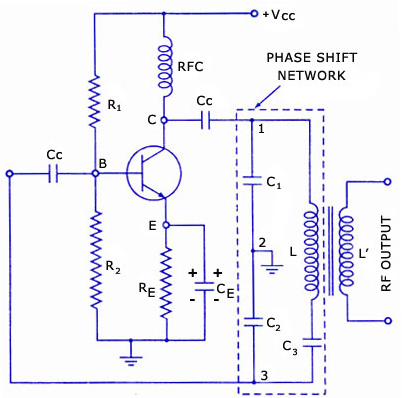
(Clapp Oscillator circuit diagram that also shows the phase shift network)
The transistor connected to this location has a Vcc power source supply. Subsequently, the power provided by the transistor quilt sets the use of the RFC coil. Using an RFC coil to kick any part of the AC component present within the power source and the most efficient supply gives DC power to the transistor circuit.
The transistor circuit schematic provides this power to the phase switch network to decoupling variable capacitor CC2. The capacitor used right here delivers the most straightforward part of the AC power to a phase-changing society. If any DC object can be implemented into the entire phase shift transfer community, it will discount the coil’s Q-factor.
The transistor stop system attached to the Resistor RE strengthens the stability of the power separation circuit. The capacitor has a connection similar to this stopping system that passes the AC inside the actual course.
The amplified power generated in a magnifier will come from the other side of capacitor C1.
Meanwhile, the renewable response transmitted to the transistor circuit can be through capacitor C2. Its miles are noteworthy that the voltage across the capacitor C1 and C2 can be in the opposing phase.
The total volume power of capacitor C1 can also be within the same phase as the power output generated with the help of a magnifier circuit. The power output of the C2 corresponds to the stage and the magnitude of the force within the amplifier circuit. This voltage at the opposing part flows to the amplifier as the amplifier circuit also provides phase switching at one hundred and eighty degrees.
Therefore, the response signal that already has part of the change of one hundred and eighty diplomas gets its transmission through the magnifier. After that, the conversion of the whole phrase can be 360 degrees which is an essential condition of the oscillator circuit to provide collision.
Those basic oscillator configurations are highly reliable and therefore popular despite having a limited range of total performance.
3.The frequency of the Clapp oscillator

(Frequency of oscillation in a Clapp oscillator)
The Clapp oscillator uses one inductor and three capacitors to set its frequency variation. However, the Clapp oscillator is similar to a Colpitts oscillator with a capacitive voltage divider that generates a response signal. The frequency of the oscillator is relative to the formula and can determine the exact oscillation frequency.

The capacitors C1 and C2 are kept organized while capacitor C3 converts targets. The capacitance value of C3 is much smaller than that of both C1 and C2, making it equal. Thus the scale up to C is approximately equal to C3, and the formula gives the oscillation frequency.

(Shows more on calculations and circuit diagrams of the Clapp oscillator)

4.Simply Explore how to Build a Clapp Oscillator
(Building a Clapp oscillator)
Consequently, from the above formula, The Clapp oscillator depends on the capacitance C3. One should also note that the price of capacitance C3 should be less than the value of capacitance C1 and C2. This is because if the capacitance C3 has a small charge, then the size of the capacitor can be small.
Select standard values from the component values of your resistance resistors R1 and R2 so that with an emitter resistor R3set up to 470 Ω, the current collector on the NPN transistor Q1 is approximately 1 mA. C1 = 1 nF and C2 = 4.7 nF are the starting points. The oscillator’s resonant frequency setting can range from about 500 kHz to 2 MHz depending on the selected values of C1, C2, C3, and L1. Calculate the value of C3 and select the closest value to your kit parts. At the highest frequency defined by the selected L1 value, this oscillator circuit may provide a sine wave output frequency of more than 10 Vpp.
When choosing a c3 capacitor, you have to be very careful. When selecting a tiny capacitor, the switching part network may not be strong enough to add strong oscillations where it should be below C1 and C2. It also needs to have a balanced reaction to provide change.
5.Clapp Oscillator Applications
(Clapp oscillators mounted on a Printed Circuit Board)
- We can use it in programs where a pervasive variety of frequencies are set to vary. For example, the receiver tuning circuits for frequency tuning.
- Used for packages wherein undamped and continuous oscillations are favorable for functioning.
- This oscillator has usage in conditions in which it’s far supposed to withstand high and low temperatures regularly.
Summary
In summary, this article has set out to look at many areas of the Clapp oscillator. It is important to note that Clapp oscillators are highly preferred because of their reliability. Due to low frequencies, the Clapp oscillator can increase its frequencies by enclosing the electronic device, including the oscillator in a constant temperature zone. In case of any question or additional information, similar to please get in touch with us.


