Contents
Introduction to Class C Amplifier
It is a category of amplifiers that operates using a transistor for current conduction. The active element (transistor) conducts a current of less than half of the input signal’s cycle. Importantly, this cycle means that the conduction angle is less than 180°, and the values always range from 80° to 120°. This conduction angle brings about so many distortions. However, it also increases efficiency since the maximum class C amplifier efficiency is 80%.
Working Principle of Class C amplifier
The circuit diagram
A tuned load controls the distortion since the conduction angle is less than 180° and brings about distortion. Additionally, this control happens by directing a current and applying an input signal to switch the transistor. Example use in an RF amplifier.
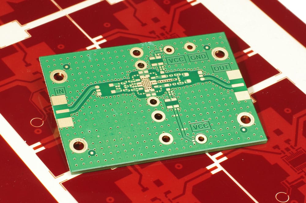
(an RF amplifier)
The diagram below shows the input waveform and the output waveform.
Principle introduction
A resonant circuit load primarily drives this amplifier. We use a negative power source to bias the circuit. Since the AC voltage source’s peak value is more significant, the base voltage crosses the base-emitter junction’s potential emitter value. Moreover, this occurs for a shorter time interval at the positive peak of each cycle. During this time, the transistor is off. But if you use a complete AC load line, the ideal maximum collector current will be Ic(sat). Additionally, the lowest collector voltage will be Vce(sat).
The transistor, which is the active element, produces a bunch of current pulses. Then, the vibrations conform to the input current, which flows through the resonant circuit. Consequently, the resonant frequency causes the tank circuits to oscillate, and it is done when we select the proper value. Finally, the tank circuit attenuates all other frequencies, making it oscillate in one frequency.
We use a suitably tuned load to obtain the required frequency and additional filters to eliminate the output signal noise. Also, we use a coupling transformer to transfer power from the bag to the tank circuit.
(battery chargers with coupling transformers.)
Class c Amplifier Advantages and Disadvantages
Advantages of class C amplifiers.
- The amplifiers are excellent in Radio Frequency applications.
- Class C amplifiers have the smallest physical size for a given power output.
- Also, they have a high frequency.
Disadvantages of Class C amplifiers.
- Fairly tricky to get perfect inductors and coupling transformers from the class c amplifier.
- The dynamic range is small.
- Additionally, it has the lowest linearity (unsuitable for use as a linear amplifier)
- Also, creates a lot of RF inferences.
- Unsuitable for audio applications due to the high levels of distortion it produces.
Class c Amplifier Output Features
The output current.
The output current of the class C amplifier equals 0 for more than half of the input signal sinusoidal cycle. Moreover, it is where the transistor remains idle at its cut-off point.
The output current maximum value.
The established theoretical efficiency of a class C amplifier is at 80%. It is because of a reduced conduction angle that increases efficiency, and it causes significant amounts of distortion. Also, the conduction angle is <180°, which ranges between 80° to 120°.
The output efficiency calculation
The formula to calculate the efficiency (η) is;
Efficiency(%)=power output x 100%
power input
Class c Amplifier Work Operation
Class c amplifier power dissipation
The power dissipation of this amplifier is lower because it only operates on a portion of the input waveform. There is a time interval between AC input signal pulses(T). Its amplitude is Ic(sat). Additionally, the minimum voltage amplitude is Vce(sat).
PD(on) = Ic (sat)Vce (sat) is the power dissipation for the transistors.
Notably, the transistor remains operating for the remaining time interval.
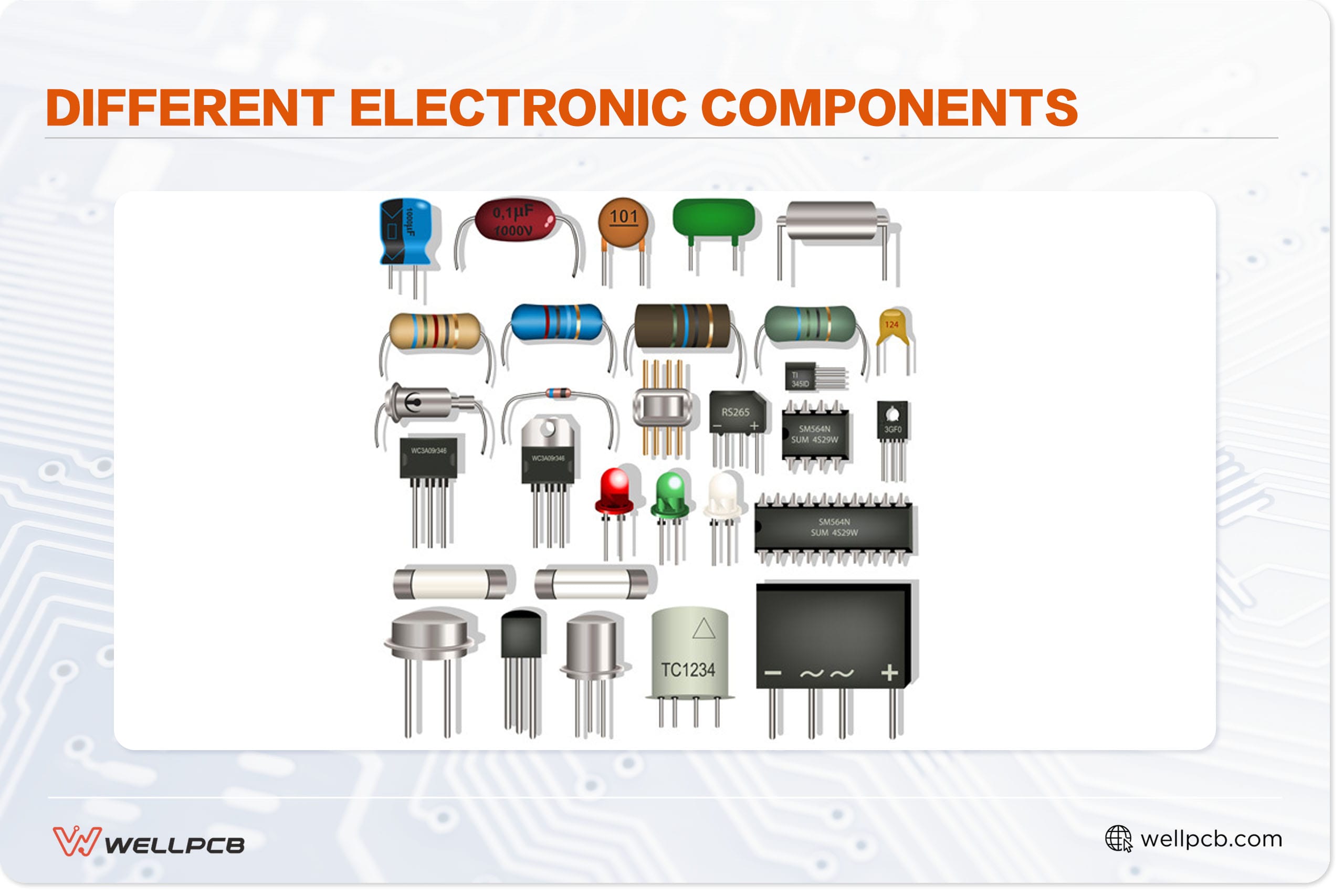
(example of transistors)
Class c amplifier tuned operation.
The collector flows for less than half of the AC signal cycle during a Class C amplifier operation. A class C amplifier has a bias of 80° to 120°.
This explains why it uses only less than 50% with a resonant circuit that operates for the complete cycle of the resonant frequency.
Because efficiency broadly rises when we lower the conduction angle, a give-and-take situation between efficiency and distortion occurs. However, it causes a considerable distortion.
A tuned load on the amplifier performs the required distortion regulation. Moreover, the active device (transistor) switches by the input signal, and the current flows through a tuned load.

(RF transmitter)
Clamper bias for a class c amplifier

(Tuned_Class_C_Amplifier_with_clamper_bias_circuit)
The above circuit layout depicts a common-emitter class C amplifier with a load resistor. To clarify, we use the resistive load to demonstrate the concept because a resonant circuit load operates the amplifier. So, with the negative source supply, biasing occurs below the cut-off point. The AC source voltage peaks are slightly higher than the base voltage. And allows the base voltage to briefly exceed the barrier potential of the base-emitter junction near the positive apex of each cycle. Notably, the transistor turns on during this brief period.
Application of Class C amplifier.
- Firstly, used in an RF oscillator.
- Secondly, used by FM operators.
- Thirdly, they are used as booster amplifiers.
- Additionally, it functions as a high-frequency repeater.
- Lastly, they are used as tuned repeaters.
Differences Between Class A, B, AB, and C amplifiers
| Differences | Signal production | cycles | Efficiency | Applications |
| Class A | provides sound signal reproduction. | Provides complete 360-degree rotations. | The transistor is always halfway on. Current always flows, thereby generating a lot of heat, leading to an efficiency of 25% | The positively biased transistor will conduct the positive signal while another identical transistor is off. Additionally, when a negative signal passes by, vice versa happens. The alternate switching of the transistor pairs distorts the output signal, generating less heat, thereby increasing the efficiency to 78% |
| Class B | does not produce a good signal reproduction | provides half cycles. | Combines the strengths of class A and B, having a sound signal reproduction and a complementary efficiency of 78% | Great for battery-powered devices |
| Class AB | has a sound signal reproduction | more than half the cycle. | Used in a high-fidelity audio amplifier. | Highly distorted output signal since the transistor is heavily biased and only turns on for <180° of the input cycle. It makes it produce less heat. Therefore, making the efficiency of class c to be 80% |
| Class C | – | Less than half the cycle. | Unsuitable for audio applications because the current pulse makes it useful in RF oscillators. | Unsuitable for audio applications because the current pulse is making it useful in RF oscillators. |
Summary
Class c amplifiers are the most efficient amplifiers to use in appliances since they produce less heat.
We hope this article is helpful to you. For any questions regarding the class C amplifier, please get in touch with us.