A current limiting circuit aids in power supplies by ensuring overall protection where there may be an overload or short circuits.
Generally, you will find current limiters fitted in electronic components to prevent future damages during power supply. They are among the standard features needed in regulating power supplies Integrated Circuits (ICs).
The above and more are what we are about to expound on in this article.
Contents
1. What is the Current Limiting Circuit?
In simple terms, current limiters prevent damage to circuits by limiting currents from a regulated power supply. In this way, the only maximum level of current an electronic circuit can determine will be applicable in the long run.

(electronic circuitry)
So, why do we need the current limiter then?
Because you can use the current limiters in several applications, it is best to ensure the electronic components’ longevity and safety. Eventually, you will have current protection on the devices.
Often, you will use the current limit circuits in linear power supplies or even apply the sensing techniques in switch-mode power supplies. Other times, you can use the current-controller circuit in operating a high-watt LED.
We will touch on both applications as we proceed.
2. Types of Current Limiting Circuit
There are a variety of current limiters you can choose from as per your project. However, the commonly used ones are the types below.
Constant current limiting
Technologists consider constant current limiting the most basic form of current limiting when regulating power supplies.
Mechanisms of action: A constant current limiter works by maintaining the output voltage as the current rises to a maximum level. When the current gets to its peak, it will be on constant maintenance. Then, a fall in voltage with increasing load will occur.
Some of its advantages include;
- It is a simple circuit with understandable circuitry.
- Additionally, it only requires a few electronic components.
As for the disadvantages;
- Whenever there is a short circuit, it does not reduce the current. It maintains the circuit current at a maximum level which can result in some damages to the circuitry.
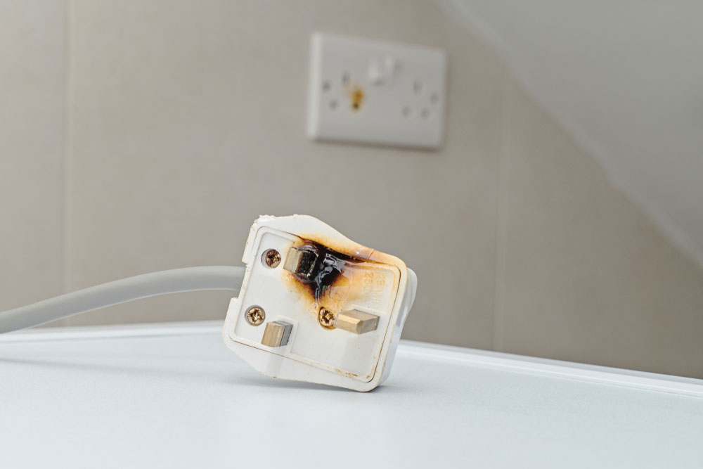
(short circuit resulting in damages)
- Moreover, when the current limiting begins its action, you will manage to draw the maximum current. In the process, however, the output voltage falls, which leads to an augmented voltage across the series pass transistor in power supply regulation. Subsequently, there is an increase in power dissipation within the electronic device.
- Thirdly, when it gets to a nearly zero output voltage and a drawn maximum current, the voltage almost always equals the initial input voltage from rectifier circuits and smoothing.
Unfortunately, such a state during an electronic circuit design stage is not recommendable. It is because there will not be an allowance made, therefore forcing the incorporation of a larger series pass transistor.
Also, you might need an extra heat sink capability which subsequently adds to the size and cost of the regulated powers supply.

(heat sink for heat dissipation in a printed wiring board)
A Fold-back current limiting
The fold-back current limiting ensures the maintenance of the output voltage till the action start of the current limiting. In doing so, the current starts going down, alongside limiting the current. Conventionally, a higher power overload leads to a reduced current, hence reducing the chances of electric circuit damage.
Some of its merits include;
- First, it reduces power consumption since the increasing overload causes the current to fall back. As this takes place, the power consumption diminishes, and the heat dissipation of the series pass transistor is at a commendable limit.
- Then, you can implement its usage in a few electronic components.
- In addition, it is cost-effective. Mostly, fold-back current limiting incorporation into regulated power supply integrated circuits is an unavoidable feature. Thus, being a requirement makes the cost almost unnoticeable.
Demerits;
- The fold-back limiter is more complex compared to a constant current limiter since it requires more electronic components. It also means additional complexity to the linear power supply.
- Secondly, it does not work well with non-linear loads.
- Further, a lockout can occur when you use the limiter with a non-ohmic device. Concurrently, the devices tend to draw continuous current levels independent of the supply voltage.
N/B – To help avoid the lockout condition, the fold-back current limiter mat includes a transient delay.

3. Calculating the Current Limiter Resistor
(application of resistors in electric components)
To calculate the current limiter resistor, we will need to look at the figure below. The figure displays a variable resistor that you can use to set the current control.
For the R1, you can replace it with a fixed resistor by calculating it with the indicated formula:
R1 (limiting resistor) = Vref/current
Alternatively
R1 = 1.25/current
R1 wattage = 1.25 x current
Note: different LEDs may have different currents, and you can calculate it by dividing the optimal forward voltage by its wattage (watt standard voltage (at 3.3V)).
For example, a 2-watt LED would have 2/3.3V = 0.6 amps or 300 ma.
The calculation also applies to other LEDs.
- Application of a Current Limiting Circuit
For this part of the article, there is a discussion on using a current limiting to design a LED current speed circuit.
Importance of current speed circuit for LED
LEDs produce illuminations efficiently and at low consumptions. But sometimes, their performances can be affected by current and heat. It is particularly true when considering high-watt LEDs since they produce a lot of heat.
The LED, driven with high currents, gets hot past its tolerance, then gets damaged. On the other hand, uncontrolled heat dissipation will eventually start drawing more current and also undergo destruction.
Therefore, current limiting helps curb the problems at hand.
Application Circuits – designing a current-controlled LED tube-light
You can use the current speed circuit to efficiently make current-controlled LED tube light circuits with high precision. For instance, in connecting a 30-watt constant current LED driver circuit, you will use the formula below to calculate the connected series resistor.
R = (supply voltage – Total LED forward voltage)/ LED current
R (watts) = (supply voltage – Total LED forward voltage) x LED current
If you lack an IC, you can opt to configure Bipolar Junction Transistors or a few transistors to form an operative current controller circuit for your LED.
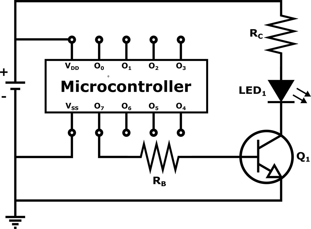
(LED controller with a transistor)
Practical ways by which you can design include;
Using two diodes and a resistor
diodes types as electrical components.
The power supply circuitry will use the emitter of the output pass transistor with a sense resistor found in the series. Then, you will place the two diodes between the transistor’s base and the circuit’s output to achieve the current limiting effect.
As the circuit operates on a normal range, a small voltage exists across the series resistor.
The small voltage and base-emitter voltage are often too small to turn on the two diode currents, as two diode junction drops would—nonetheless, an increase in current results in a voltage increase across the resistor.
There must be an equal base-emitter junction drop and resistor for the two diodes to conduct current, which ultimately equals two diode junction drops.
Calculating resistors
You will determine R1 by the following formula:
R1 = (Us – 0.7) Hfe/Load Current
Us = supply voltage
Hfe = T1 forward current gain
Load current = Led current = 100W/35V = 2.5 amps
As for R2:
R2 = 0.7/LED current
Conclusion
In summary, electronic devices with permanent power require safety measures to keep running for a long time. Also, the safety measure should utilize fewer additional electronic components, be cheap, and be simple to implement in the devices. A current limiter fits in all the categories mentioned here.
What’s more, you can integrate it yourself as you set your project. If, however, there are any queries you may have, contact us. We will be glad to help.


