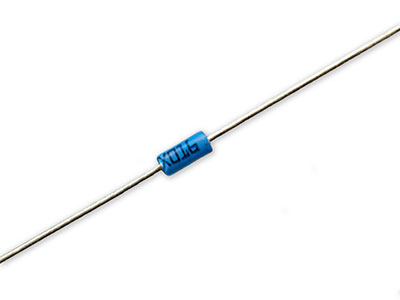
It’s common to find the DIAC in applications like the universal motor speed control, AC lamp dimmer, etc. And it’s because the semiconductor helps to control current until it reduces below the devices’ holding current level.
So, the DIAC does not enter a low current level. Somewhat, when it enters conduction, the voltage reduces per increase in current. No doubt, this semiconductor belongs to the thyristor family, but it’s more like a bidirectional wide-range trigger device.
Do you want to learn more about DIACs? Then, stick around because we’ll take you through the basics like its layer structure, how it works, etc.
Let’s get to work!
Contents
What is DIAC?
DIAC is an acronym that stands for Diode for Alternating Current. And the solid-state device features two-junction semiconductors and three layers.
At first glance, you may mistake the DIAC’s structure for a transistor. But the difference is that the former doesn’t have a terminal at the base layer. Hence, it’s a two-terminal device (A1 & A2).
The DIAC doesn’t provide amplification; instead, it behaves like a bidirectional switching diode. Plus, the DIAC direct current comes from either polarity of an appropriate AC voltage supply.
Further, the DIAC comes in different packages like surface-mount packages, huge packages combined with chassis, small leaded packages, etc.
What’s the Symbol of DIAC?
You can represent the DIAC with two diodes that connect in parallel. But the diodes should be opposite to one another. Also, the device features two terminals (Anode 1 and Anode 2).
In addition, you can also denote the main terminals with MT. Further, the airports are reversible like capacitors because they are bidirectional. Plus, the DIAC doesn’t have a gate terminal.
DIAC Construction
Like we mentioned earlier, the DIAC construction is similar to the transistor. But it stands out because it doesn’t have a base terminal. Also, the DIAC’s three layers have an equal amount of doping. Plus, it provides symmetrical switching properties—in the applied voltage’s polarities.
That said, the semiconductor layers that are close to the terminals combine negative and positive layers. Hence, when you pass voltage to the device’s airports, the layer with the specific polarity to the voltage activates. And the fusion of both the polarities aid in the DIAC’s bidirectional operation.
DIAC Operation
If the A1 or MT1 terminal is positive, it will activate the P1 layer close to the MT1 airport. Hence, conduction will happen in a particular order: P1-N2-P2-N3.
That said, the moment that current moves from MT1 to MT2, the junction between P2-N3 becomes reverse biased. Also, the second junction between P1-N2 will be forward biased.
In the same way, if we have a positive MT2 terminal, the P2 layer that’s close to the second terminal (MT2) activates. Hence, the conduction will occur in this order: P2-N2-P1-N1.
So, when the current moves from MT2 to MT1, the junction between N2-P1 is reverse biased. But the links between P1-N1 and P2-N2 are forward limited. Thus, conduction will occur in both directions.
What are the V-I Characteristics of DIAC?
Since the DIAC conducts voltage in both negative and positive polarity, the curve lies on two quadrants (first and third). Hence, the V-I characteristic curve forms a Z shape.
That said, the first quadrant indicates the positive half cycle where current moves from MT1 to MT2. On the other hand, the second quadrant shows the opposite—the negative half cycle where recent activities from MT2 to MT1.
At first, the DIAC’s resistance tends to be higher due to the reverse Bias junction between the layers. Consequently, a small leakage current will move through the DIAC. You can refer to this area as the blocking state in the curve.
Also, when the applied voltage gets to the breakdown voltage, the DIAC’s resistance reduces sharply. When this happens, conduction will begin, and it will cause an instant decrease in voltage—while current rises (conduction state).
Further, it’s normal for most of the DIAC’s to experience a breakdown voltage of around 30V. But the specific breakdown voltage depends on the type of device you use.
So, the DIAC will remain in the negative half-cycle (conduction state) until the current gets to a specific value (holding current). The holding current refers to the minimum current that the device needs to remain in the ON state.
How Do You Use a DIAC?
Most times, you can use the DIAC with the TRIAC circuits. And it’s because of the TRIAC’s shortcomings. That is, the TRIAC has a slight difference between the two halves of the device. Hence, the device doesn’t fire a circuit symmetrically.
Due to the TRIAC’s non-symmetrical firing, the waveform produces the output with unwanted harmonics.
So, the more non-symmetrical the waveform is, the higher the harmonics. Thus, the best way to have a symmetrical waveform in both cycles is by connecting the DIAC in series with the TRIAC’s gate.
Also, the DIAC helps avoid the flow of gate current until the applied voltage reaches a certain level in any direction. With this, the TRIAC’s firing point will be more uniform in both directions.
DIAC Application
Since the DIAC is majorly a trigger device, you’ll find it in applications like:
- Heat control
- Light dimmers
- Control circuits of motor speed control
Here is how it works in these circuits:
Light Dimmer Circuit
First, you can get the variable gate voltage by making an RC arrangement at the TRIAC’s gate terminal. Then, when the device goes off, the voltage rise is limited by the series network (R4-C1) across the TRIAC.
So, when you apply the input voltage to the circuit, resistance R2 determines the charging rate of C1 and C2. Also, the DIAC triggers and conducts when the voltage across the C3 goes beyond the DIAC’s break-over voltage.
Additionally, the capacitor C3 begins to discharge via the conducting DIAC into the TRIAC’s gate. Hence, when the TRIAC comes on, it passes current to the lamp. Plus, the capacitor’s rate of charge varies by changing the resistance R2.
Consequently, the voltage at the TRIAC triggers both negative and positive cycles of the controlled input. Overall, the DIAC helps to regulate the power fed to the lamp.
Heater Control Circuit
With the DIAC here, the heater will have smooth control of its heat. First, join the LC across the TRIAC—to decrease the rate of voltage increase when the TRIAC is off.
Then, you can regulate the half-cycle (negative and positive) of the heater’s input voltage by modifying the resistance R2. So, you can get a smooth control of different R2 positions by putting R4 diagonally to the DIAC.
Difference Between DIAC and TRIAC
| DIAC | TRIAC |
| 1. It has two terminals (MT1 and MT2) | It has three terminals (MT1, MT2, and Gate) |
| 2. The bidirectional device allows current flow in two directions—when the voltage across gets to the break-over voltage. | The TRIAC is also a bidirectional device that permits the current to move when you trigger its gate. |
| 3. This device has less power handling capacity. | TRIAC has a higher power handling capacity |
| 4. DIAC appears to be a combination of two diodes in inverse parallel. | On the other hand, TRIAC joins two SCRs in inverse parallel—and the gate terminals of each SCR form the TRIAC’s GATE. |
| 5. DIAC shows negative resistance features. | TRIACs don’t show negative resistance characteristics—that’s why it has many AC circuit applications. |
| 6. When you apply a voltage across its two terminals equal to or more than the break-over voltage, the DIAC triggers. | You can trigger the TRIAC by adding a voltage (negative or positive) at the gate terminal. |
Pros and Cons of DIAC
Pros
- The device provides smooth power control with TRIAC and other thyristors
- It comes with symmetrical switching characteristics
- You can switch it easily by decreasing or reducing your applied voltage
- DIAC helps to reduce unwanted harmonics in a system
- It features a low on-state voltage drop
Cons
- DIACs can’t block high voltage
- The device can only conduct with a voltage above 30V
- The DIAC has low power
Final Words
The DIAC is a powerful device that triggers and conducts voltage in a few applications. And it’s all thanks to its symmetrical switching features. But it works alongside the TRIAC to get the best results.
So, are you planning on using DIACs for your next project? Or do you have questions on how to use the device effectively? Please feel free to contact us.


