Contents
What Are Input Signals?
Signals allow different devices to interface and communicate.
For this to happen, they must be able to exchange information or data.
Ultimately, signals serve as electric conduits to transport this information.
Digital and Analog input refers to the type of signals a device or port accepts.
Typically, an output device sends an outgoing signal to an input device.
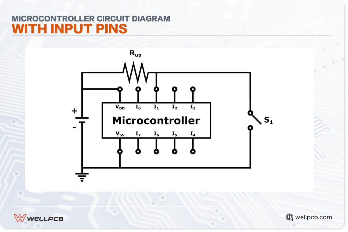
Microcontroller circuit diagram with input pins
What are Digital Input Signals?
Digital input signals carry an inconsistent flow of discrete data. Typically, they’re halting and non-consistent.
For instance, a digital signal with binary values can have either one (high-level) or zero (low-level).
Thus, square waves typically represent the structure of these types of input signals.
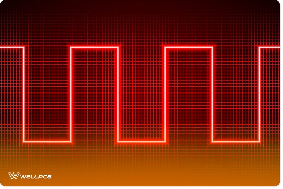
Digital Input Signal
They are the most widespread type of input for modern PLCs.
This is because they have high bandwidths, making them ideal for computing.
They’re also resistant to noise, which makes them highly accurate.
What are Analog Input Signals
Analog input signals carry consistent or continuous waves of data. Thus, they are often represented by sine waves:
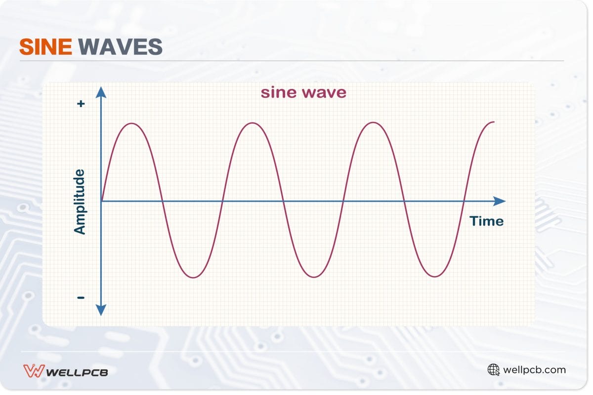
Sine Waves
The most common forms of analog input signals include (but are not limited to) temperature, voltage, and current.
General Purpose Input/Output
You may have noticed that some microcontrollers and SBCs have General Purpose Input Output pins.
As the name suggests, these devices can use these pins to either receive signals (input) or send signals (output).
Software on the device controls whether it outputs or accepts signals.
Moreover, these devices come with analog-to-digital converters (ADC) to convert analog input signals into digital signals.
Often, this is how values from pressure and temperature sensors become represented as digital ones.
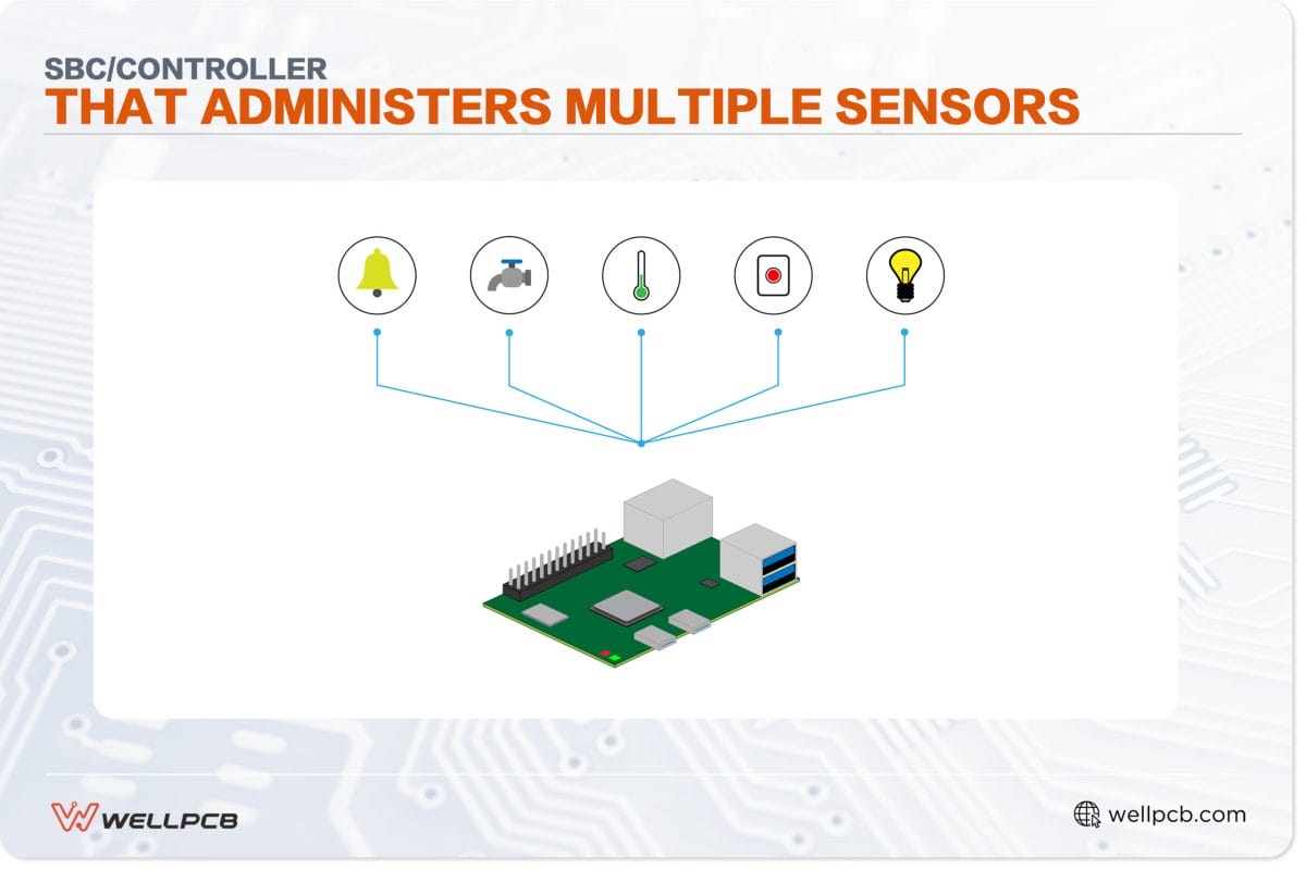
SBC/Controller that administers multiple sensors
Digital Input vs. Analog Input: Comparison Table
The following table summarizes the differences between digital and analog input signals.
| Attribute | Digital Input | Analog Input |
| Signal | Analog inputs require lower bandwidth when compared to digital inputs. It’s one of the few advantages analog inputs have over digital inputs. | Analog inputs use a continuous signal. |
| Physical Representation | We usually represent digital inputs as a square wave. | Analog inputs usually come in the form of sine waves. However, on rare occasions, they may also present themselves as triangle waves. |
| Bandwidth Requirements | Digital input signals are highly resistant to electronic noise, making them more reliable and accurate than analog input signals. | Analog signals are highly susceptible to electronic noise. PCBs and circuits can experience sudden changes (such as spikes or dips). This causes noise. In such circumstances, analog signals’ current can be disrupted, rendering them inaccurate. |
| Suitable Applications | Ideal for communications between computational machines and digital electronics. | Analog input signals are ideal for media applications and sensor information. This includes audio, video and various forms of measurement data. |
| Susceptibility to Electronic Noise | In computer peripherals such as keyboards. They send digital signals to and from your computer in a stream of binary numbers to and from your computer. | In computer peripherals such as keyboards. They send digital signals to and from your computer in a stream of binary numbers. |
| Power Consumption | Because digital inputs do not transmit in a single continuous stream, they’re more power efficient than analog input signals. | Analog signals transmit in a single continuous stream. Thus, they have relatively high power consumption. |
| Circuit Components | In computer peripherals such as keyboards. They send digital signals to and from your computer in a stream of binary computer and from your computer. | In computer peripherals such as keyboards. They send digital signals to and from your computer in a stream of binary Computerand from your computer. |
| Use Cases | In computer peripherals, keyboards. They senrom your computer in a stream of binary numbers to and from your computer. | Electric fans, sensors and volume controls for radios are some of the most widespread uses for analog signals. |
Conclusion
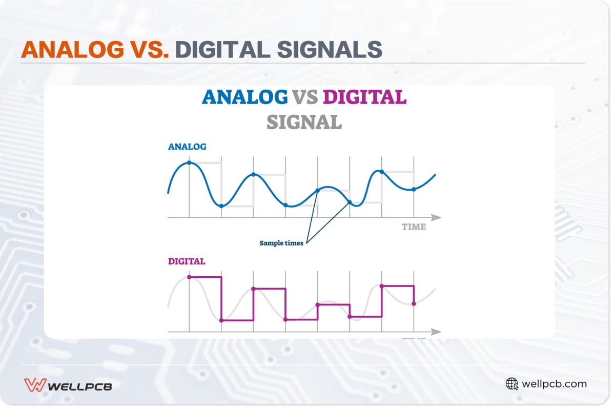
Analog vs. Digital Signals
The above guide examines digital input vs. analog input signals. Suffice it to say that these signals differ in their purposes and usages. Technically, no signal is better than the other.
Although digital signals are far more power-efficient, accurate, and reliable, analog input signals still have their place worldwide.
For instance, we can still use it to carry video and audio data.
Furthermore, many devices come with analog-to-digital converters and even digital-to-analog converters.
Nevertheless, if you want to learn more about PCB-related technology such as these, don’t hesitate to contact us or visit the rest of our website.


