

A Diode Voltage Clipper
Source: Wikimedia Commons
Contents
What is a Diode Clipping Circuit?

A Diode Waveform Clipper
Source: Wikimedia Commons
The diode clipper is a wave-shaping circuit. And it works by taking an input waveform. Then, it cuts both halves, the top or bottom half—depending on the diode’s features. You can also call this device a diode limiter.
When the diode clipper cuts or clips an input signal, it generates an output waveform that looks like a flat version of the input.
So, you can use the diode clipping circuit for different applications to reform an input waveform with Schottky and signal diodes.
Or the circuit uses Zener diodes to deliver over-voltage protection. Consequently, the diode clipper will guard the circuit against high-voltage spikes.
That way, it will ensure that the output voltage doesn’t go beyond a particular level.
That said, a resistor and ideal diode are the essential components you need to build a clipping circuit. But while you’re at it, adding a DC battery is vital.
Then, you can fix your clipping level to a preferred amount.
How Does a Diode Clipping Circuit Work?
The working principle of the diode clipping circuit is similar to the diode. It permits current to pass through itself, clamping the voltage—when the diode is forward biased.
Also, no current flows through the diode when it is reverse biased. Hence, the voltage across its terminal will remain unchanged.

Category of Clippers
Typically, we have two adding: a DC battery is vital parallel and series. A similar configuration is when the diode is branched parallel to the load.
And the series configuration is when a diode and gear are in sequence.
Positive Diode Clipper

Positive Diode Clipper
Source: Tutorialspoint
When you have a positive clipper, you’ll notice that the input voltage’s positive half cycles are absent.
Also, if your diode is in series with the load, you’ll have a reverse bias during the input waveform’s positive half cycle.
As a result, the diode circuit will clip off the positive half cycle. And the output voltage will retain 0 Volts.
Then, your diode will be forward-biased when your input has a negative cycle. Hence, you’ll see the negative half process across the output.
That said, when your diode is parallel to the load, the opposite happens. In other words, the diode will be forward biased during the positive half cycle.
The diode will behave like a closed switch, conducting heavily. Hence, the voltage drop across the load resistance or diode will be zero.
Thus, the output voltage value during the positive half cycles is zero. And when the input signal has a negative half cycle, your diode will be reverse biased.
Consequently opposite happens; it will act as an open switch. And t will show across the load resistance or diode (if the resistance load is greater than the resistance).
So, you can say that the circuit acts as a voltage divider. And it has an output voltage of [RL/ R + RL] VMAX = -VMAX (when R< RL)
Negative Diode Clipper

Negative Diode Clipper
Source: Wikimedia Commons
The negative diode clipping circuit is more like the reverse of the positive clipping.
So, when your diode is forward biased and the sinusoidal waveform has a negative cycle, it clips it to -0.7 Volts.
Also, when the diode is reverse biased, it permits the positive half cycle to flow unaffected. Hence, you’ll have a negative clipper circuit when your diode limits the input voltage’s negative half cycle.
Can the diode clip both cycles?
Yes, it can. And you can start by making an inverse parallel connection of two diodes. Consequently, the first diode (D1) will clip the sinusoidal input waveform’s positive half cycle.
On the other hand, the second diode (D2) will cut the negative half cycle.
Hence, you can use the audio circuits to clip the negative and positive half cycles or the two.
That said, your output waveforms will be zero—if you use ideal diodes. But when you have a forward bias, you’ll notice a voltage drop across the diodes.
Therefore, the clipping points will happen at +0.7 volts and -0.7 Volts.
But you can get a higher value than the ±0.7 volts threshold. And you can achieve this by adding a voltage bias to the diode.
Or you can link many diodes in series—to create multiples of 0.7 Volts.
Combination Clipper
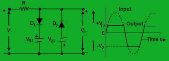
Combination Diode Clipper
Source: Researchgate
If you use ideal diodes, a combination clipper comes in handy with positive and negative half cycles.
So, when you have a forward bias and put the voltage above the (+V1) first battery’s voltage of the D1, there’s heavy conduction.
But, your D2 will be reverse biased.
Hence, you’ll see the output voltage or +V1 across the output.
Your diode (D1) will stay reverse-biased regarding the negative input voltage signal. Then, the +V1 will last for a while. Afterward, the input signal will surpass the +V1.
Also, the second diode, or D2, will have heavy conduction. But this only happens when the input voltage is more than the magnitude of the battery voltage V2.
So, the output will remain at -V2 during the negative cycle. This applies as long as -V2 is less than the input signal voltage.
Biased Diode Clipping Circuits

Biased Diode Clipping Circuit
Source: Tutorialspoint
A bias voltage is essential for generating diode clipping circuits for voltage waveforms at various levels. So, if you want your diode to be forward-biased for conduction, your VBIAS + 0.7V must be less than the voltage series across the series combination.
For instance, if you set your VBIAS level at 5.5 Volts, there can only be a forward bias when the voltage at the forward biased is more significant than 5.5 + 0.7 = 6.2 Volts. Hence, the circuit will clip all the voltage levels higher than this bias point.
Negative Bias Diode Clipping
When you vary the diode’s bias voltage, you’ll get a diode limiting level or a different diode clipping. So, you can use two biased clipping diodes to clip the negative and positive half cycles.
Also, it’s vital to note that the bias voltage for the positive and negative diode clippings doesn’t need to be the same.
For instance, your positive bias voltage could be 8 Volts, while the negative bias voltage is 10.
Positive Bias Diode Clipping
You can start by reversing your battery bias voltage and diode. Consequently, when the diode conducts at the output waveform’s negative cycle, the VBIAS will remain at a certain level.
Diode Clipping of Various Bias Levels
The diode (D1) will conduct when the positive half cycle’s voltage reaches +4.7V. Then, it will restrict the waveform to +4.7V.
Also, for the D2 to conduct, the voltage has to reach -6.7V. Hence, the circuit will automatically clip all the negative voltages below -6.7V and positive voltages above +4.7V.
That said, ensure that you don’t set the diode clipping levels too low or an input waveform too high.
Or you’ll have a square-wave-shaped waveform when the circuit removes the two waveform peaks.
Zener Diode Clipping Circuits
A bias voltage ensures you can precisely control the voltage waveform that clips off. However, the drawback of utilizing voltage-biased diode clipping circuits is that they require one more electromotive force battery source.
Hence, you can employ Zener diodes instead.
Zener diodes specifically work in the reverse-biased breakdown region. Hence, it’s ideal for Zener diode clipping or voltage regulation applications.
When the Zener conducts, it behaves like a regular silicon diode with a forward voltage drop of 700mV (0.7V) in the forward region.
Further, in the reverse bias, the voltage remains blocked until the Zener diodes’ breakdown voltage reaches.
The waveform clips at the Zener voltage when the Zener diode circuit is in reverse bias.
Also, the course acts as a regular diode with its junction value of 0.7V during the negative half cycle.
Applications of The Diode Clipping Circuit
You can use the diode clipping circuits in the following applications:
- Power supplies
- Eliminates excess ripples in signals that exceed a particular noise level in FM transmitters
- It adjusts existing waveforms and creates new ones
- You can use it as a freewheeling diode that safeguards transistors from transient effects.
- Restricts the voltage input in a device
Final Words
A diode clipping circuit effectively restricts, prevents, or cuts the input signal voltage or waveform below or above a specific level.
And there are different types of clipping circuits, depending on your goal.
That said, what do you think about the topic?
Do you need help getting the best diode clipping circuit for your project?
Please feel free to reach us.


