
Different kinds of DIY timer serve various purposes. But, despite the variety, the base still boils down to a simple timer circuit. So, you can use the timer circuit for many applications, including pulse generation and oscillators.
Plus, the design is pretty straightforward, and you can get it done within a short period. However, that doesn’t mean it’s easy to build.
That’s why we’ve created this article—to make things easy for you.
So, if you need to know how to make a DIY timer, this article is for you; we will show you how the timer circuit works and show you how to make two easy DIY timer circuits.
Ready? Then let’s jump right in!
Contents
How Does the Timer Circuit Work?
As we mentioned earlier, there are different types of timers with various applications. However, we will talk extensively about a simple but useful timer circuit that you can adjust with ordinary pots. Here’s a diagram of the circuit:
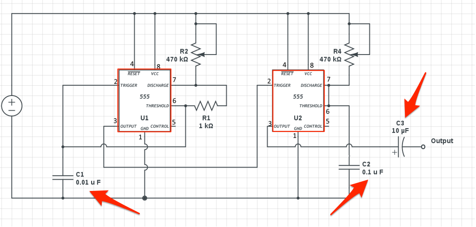
Diagram of DIY Timer Circuit
Source: Wikimedia Commons
Looking at the circuit diagram above, you’ll see two 555 timer ICs set up as independent timer modes.
Although the timing settings are different, the configuration for both 555 timers is similar.
So, how does it work?
You can couple the upper 555’s output to the lower 555’s reset input with a transistor. Then, you can connect so that when the upper 555 goes high, it will trigger the operation of the lower timer.
Thus, the lower 555 begins its count. But, when the output goes high, it stops counting, goes back to its normal state, and restarts the process.
In other words, if the timing of the upper 555 does not stop, the lower 555 will remain inactive. So, as soon as the upper 555 stops its timing, its output becomes high, thus switching the output load and activating the lower 555.
Also, you can use the pot connected to the upper 555 timers to determine how long you want the load to stay, while the pot connected to the lower 555 determines when you want the load switched off.
Additionally, you can upgrade the above circuit’s design with a push-button—and still switch on/off the timer with the push of a button. One of the upsides to using the push-button design is that it makes sure the timer gets completely turned off, especially in a power outage while the circuit is in use. It also ensures that important loads like geysers or heaters stay off in such events.

How to Build a Simple DIY Timer Switch
Earlier, we said we would show you how to make two simple DIY timers.
So, we would be looking at building a DIY countdown timer and a DIY sand timer.
DIY Countdown Timer
Here’s how to make a simple DIY countdown timer:
Step 1: Get Your Materials Ready
The first thing you need to do before doing any project is to get your materials ready.
So, for the countdown timer, here are the materials you need:
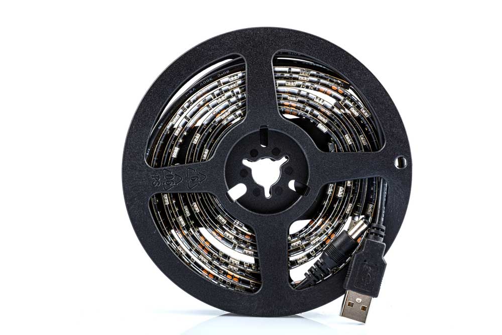
- 5v USB LED strip (1 meter)
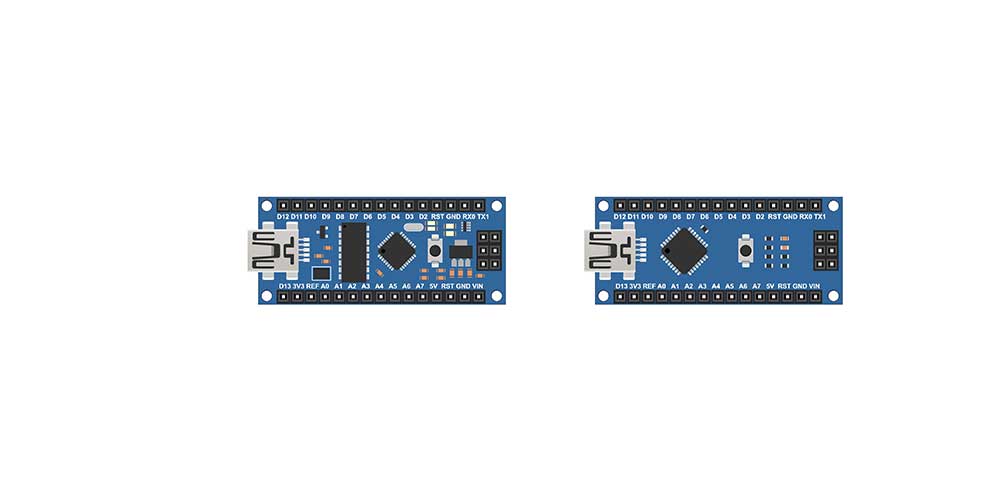
- Arduino Nano
- Polystyrene packing (1 cm thick)

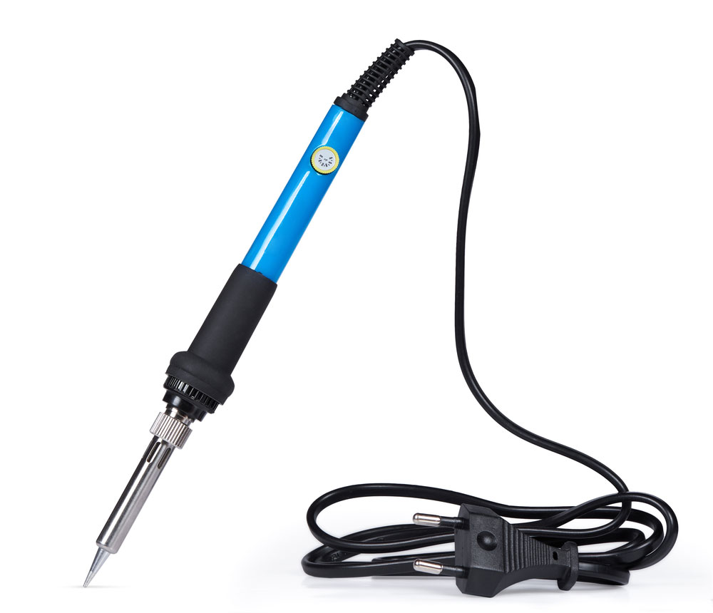
- Soldering iron
- One pole push button (double on/off)
- Wire
- Two sheets of vellum

- Hard card for display back

Step 2: Make a Light Guide
Light guides shape the glow of the LEDs. So, ensure to make your LED digits on a piece of card. Plus, you can choose to print any of the available digital style fonts.
After that, cut out the parts of the display for your polystyrene template. Plus, you can use a large tape to secure the polystyrene to the card. Then, cut out each part from the polystyrene with a sharp knife.
Step 3: Set a Base for Your LEDs
Next, set up a base for your LED display. You can use a piece of cardboard mount or any stiff material. Additionally, use the polystyrene light guide from the previous step to mark the positions of the LEDs on the base. Once that is done, stick the LED strips to the segments.
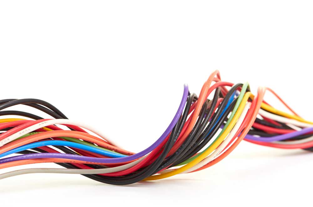
Step 4: Start Wiring
Here’s where it gets tricky. First, you must solder each LED strip to a different wire that will connect to a single Arduino pin.
Confirm that you mark each wire, so you don’t spend hours trying to tell wires apart. Also, the Arduino you’re using determines the way you connect the pins to your wires.
Step 5: Use Glue for The Polystyrene Light Guide
Secure your polystyrene light guide to the base with glue making it cover the wiring and LEDs. Add the diffuser so individual LEDs won’t be visible.
Step 6: Fix Your Start Button
Use a button that has two connections. One connection goes to the Arduino pin (+ve), while the other goes to the ground through a 100m resistor.
Step 7: Use a Code to Program Your Timer
Lastly, you can use a code to light up each segment of the required number every second or minute. Plus, you can find an efficient code for your countdown timer here.
DIY Sand Timer
The DIY sand timer is old and vintage technology.
So, here’s how to make a simple DIY sand timer:
Step 1: Arrange Your Materials
The components for this design are easy to get. So, you’ll need quick glue, a small plastic towel, sand, and two bottles with something to make a hole.
Step 2: Create Clean Holes on Both Caps
Next, create clean, smooth holes on both bottle caps.
Step 3: Join the Caps with Glue
Use glue to join the bottle caps together.
Step 4: Add a Piece of Funnel in the Hole
Insert a piece of a funnel into the holes and be precise with this step.
Step 5: Put Your Dry Sand into Your Bottle
Fill up half of one bottle with dry sand using the leftover funnel.
Step 6: Place the Connected Caps on the Bottles
Add the caps to the bottles and make sure it’s secure with some tape.
Bottom Line
One fun fact about the timer circuit is it’s programmable.
In essence, it means you can set what you want the timer to do. Furthermore, you can adjust the delay timings according to your personal preference and set them on/off delay time independently. So, it’s the crucial part of the timer circuit.
That wraps it up! If you have any questions, or you’d like more information on DIY timers, feel free to contact us.


