Pole and Throw
A pole is the number of circuits controlled by the relay. On the other hand, a throw refers to the extreme location of the actuator.
In other words, a throw is the number of connections each relay pole can have.
For example, a single pole switch controls a single electrical circuit, whereas a double pole switch controls two independent courses.
Conversely, a single-throw switch closes a circuit in one position, whereas a double-throw controls in two positions.
Now, let’s define the following terms.
Single Pole Single Throw
An SPST switch has one input terminal and connects to one output terminal, either ON or OFF. This switch has four terminals when you include the two for the coil.
Single Pole Double Throw
An SPDT switch has three terminals and connects to one of the two output terminals. This switch has five terminals when you include the two for the coil.
Double Pole Single Throw
A DPST is a switch with four different terminals or two SPST switches actuated in unison. This switch has six terminals when you include the two for the coil.
Double Pole Double Throw
A DPDT switch has two rows of change-over terminals equivalent to two SPDT switches. This switch has eight terminals when you include the two for the coil.
Single Pole Double Throw
Features
- SPDT Relay
- High Switching Current
- Normally closed relay
Schematic
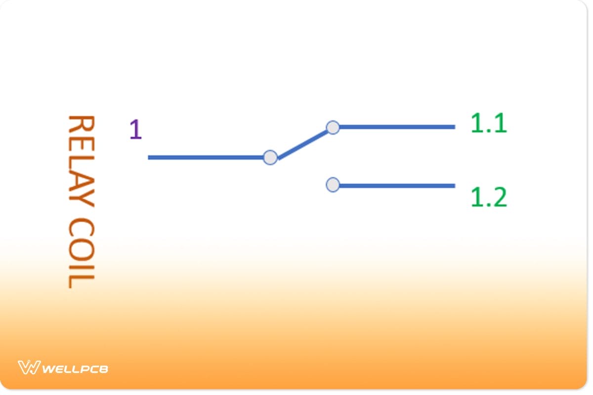
Fig 2: A Single Pole Double Throw relay diagram
How does the Single Pole Double Throw relay work?
An SPDT relay internal configuration has one control input terminal that controls two outputs. Therefore, it has five terminals: two relay contacts, one for the pole and two for the throw.
To understand more, let’s refer to the first output terminal as output 1 and the second as output 2. In a normal position, say OFF, one output is connected while the other is disconnected.
When you energize the relay (provide coil voltage), the power flow in its circuit causes the connected terminal to disconnect.
The result is that the input terminal connects to the other output terminal, energizing the circuit.
When the relay coil is not energized, one terminal is Normally Closed (NC) while the other is Normally Open (NO).
Usage
With Arduino
For use with Arduino, you’ll need a Grove-SPDT 30A relay module that’s a Normally Open switch. You can control higher current devices such as parking lights, fans, etc.
With Raspberry Pi
- For this setup, you’ll need a Raspberry Pi and Grovepi or Grovepi+.
- Also, you need to have completed configuring the development environment.
- Thirdly, use a grove cable to connect the sensor to the Grovepi socket D4.
- Fourth, go through the demo’s directory: cd your path/GrovePi/Software/Python/
- And, to see the code: nano grove_spdt_relay.py # “Ctrl+x” to exit #
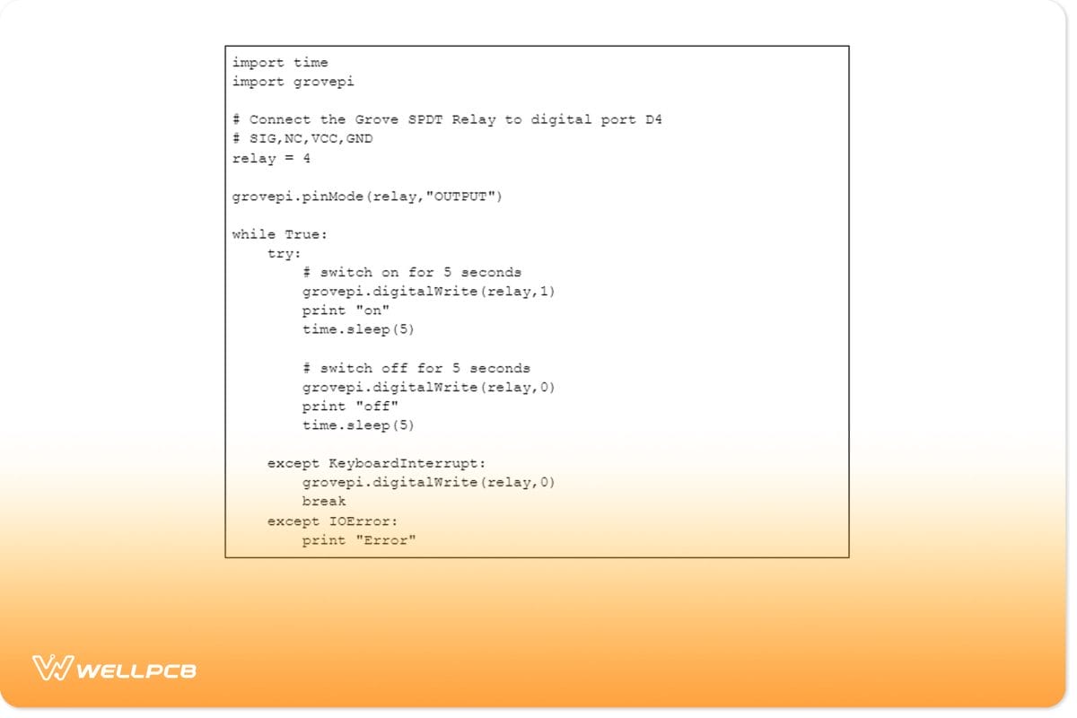
- And run the demo: Sudo python grove_spdt_relay.py
Double Pole Double Throw
DPDT Circuit Diagram
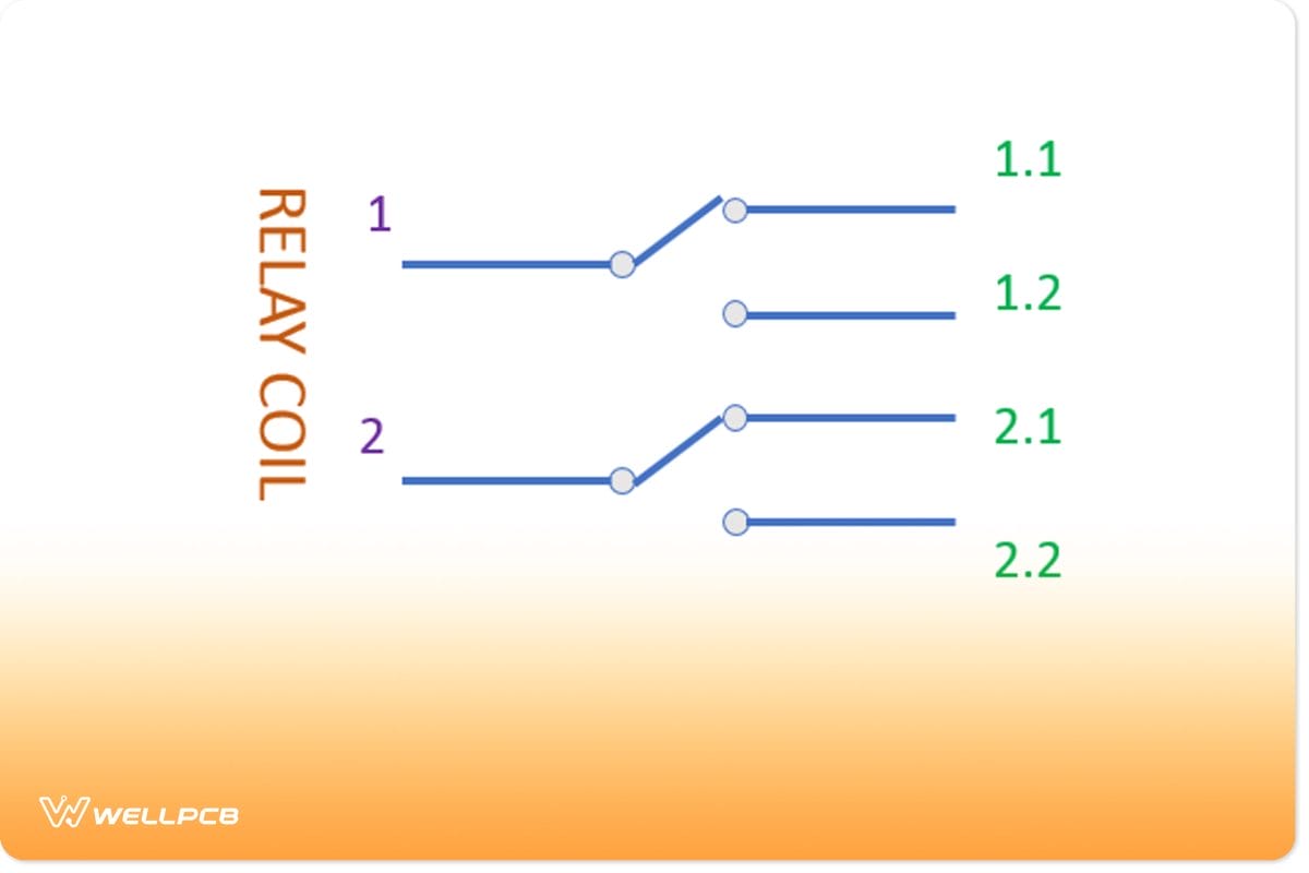
Fig 3: A Double Pole Double Throw symbol
How Does it Work?
A DPDT relay has four outputs corresponding to two inputs. Furthermore, both inputs are isolated from each other, as are both output pairs. Each input terminal connects to a Normally Closed terminal (1.1), whereas the other terminal (1.2) is Normally Open.
Similarly, the second input terminal connects to a Normally Closed terminal (2.1). Additionally, the other terminal (1.2) is Normally Open.
Usage
Change Motor Direction With the DPDT Relay
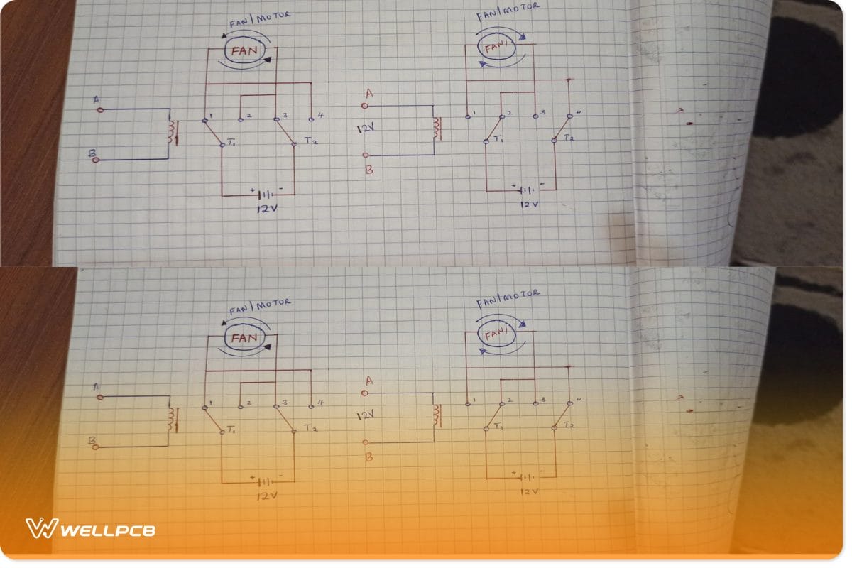
Fig 4: Changing motor direction with DPDT relay
As you can see from schematic 1, the power source has its positive (T1) and negative (T2) terminals. With the power OFF, T1 is connected to contacts 1 (and 4) and T2 to terminals 2 (and 3).
In this state, the motor is running in a clockwise direction. Powering the relay ON connects T1 to terminals 2 (and 3). It also connects T2 to terminals 4 (and 1). In this state, the motor runs anticlockwise.
Switch Between 2 Different Loads with a DPDT Switch
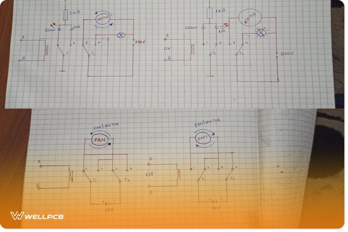
Fig 5: Switching between two different loads with a DPDT switch
Instead of ON/OFF, we can use the same circuit to power two different loads. In our case, we can opt to turn ON either the motor or fan, but not both.
When the relay coil is unenergized, the fan is ON, and the green LED is ON. Conversely, when the relay is energized, the red LED is ON, and so is the motor.
Conclusion
Unlike other control circuits and devices, the relay is simple to implement, cheap to buy, durable, and reliable. You can use it for small remote switching or even high-power control circuits.
But first, you need to know its rating and whether it’s compatible with your circuitry. Finally, contact us if you need more clarification on relays and related circuits.