
Timers are essential in the home and industrial automation applications such as ovens, microwaves, washing machines, etc. With the growth of automation and the need for precision, more engineers prefer electronic timer circuits.
Traditionally, one had to flip a switch or press a button to turn a circuit ON or OFF. However, manual operation was prone to error, hence the need for accuracy. If you have a timer project in mind, you’re in the right place.
We’ll guide complete the various electronic timer circuits you can use.
Contents
Electronic Timer Circuit Using CD4060
Circuit Diagram

Fig 1: Electronic Timer Circuit with CD4060
Components Needed

Circuit Explanation
The circuit functions on a CD4060 CMOS chip with an inbuilt oscillator and binary counter. We use the variable resistor in our circuit to vary the period before the alarm rings. Also, our design has a reset switch that enables you to reset the alarm when needed.
Here’s how you can set up your circuit:
First, set up the internal oscillator stage using a network of resistors and a capacitor. Connect a 1uF timing capacitor to pins 9 and 11 and pin 10 with a timing resistor. And, since you need to vary your frequency range, you must use a variable resistor at this stage. Also, it would help if you connected a fixed resistor to pin ten so the values don’t get to zero.
When you power your circuit, a pulse at the junction between C2 and R3 resets the counter. Consequently, it starts counting up to bit 14, setting pin 3 high, and the buzzer turns on. To turn it off and start the oscillations all over again, press the reset switch S1.
To change the oscillator’s period, change the values of the R1, R2, and VR1. However, ensure that the total resistance to pin 10 is ten times less than the value of the resistor to pin 11.
Simple IC 555 Timer Circuits
Circuit Diagram
Fig 2: An integrated circuit
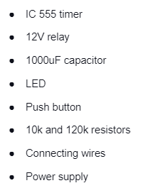
Components Needed
Circuit Explanation
The IC 555 timer circuits rely on three 5K resistors to produce a voltage divider at pins 1 and 8. The circuit diagram above is for a one-minute timer based on the IC 555. To get varying times, all you have to do is adjust the values of the resistor R1. Additionally, the timer is in a mono-stable mode and starts timing when you power the circuit. When the one-minute duration elapses, the LED turns ON automatically.
Generally, we can get the time during which the IC 555 timer pin 3 remains high using the formula:
T = 1.1*R1*C1
For example, a 1000uF capacitor gives us a resistance of 55K at R1.

Consequently, set your potentiometer to 55k.
Here’s how to get a 5-second timer circuit resistor with a 1000uF capacitor

Consequently, set your potentiometer to 4.5k.
Timer Circuit using Single Transistor
Circuit Diagram

Fig 3: An electronic timer circuit with one transistor
Components Needed

Circuit Explanation
The above on/off timer circuit diagram uses a single 2N3904 transistor and a 12V relay. Powering the circuit causes the transistor to activate the timer for a duration set by the relay. The electrolytic capacitor sets the relay, and increasing capacitance to 1000uF increases the ON time to 2.5 minutes.
Using a Pair of Transistors
Circuit Diagram
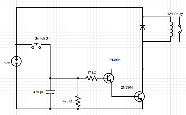
Fig 4: An electronic timer circuit with a pair of transistors
Components Needed

Circuit Explanation
Here, provide your transistor with a base resistor to limit the current through the base and determine the ON time. However, using a single transistor result in a time delay of a few seconds and may be insufficient for more extended periods. Therefore, you can add another transistor stage to increase the circuit sensitivity and, consequently, the time delay.

Timer Circuit using a Darlington Pair
Circuit Diagram

Fig 5: Electrician checking transistor voltage
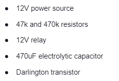
Components Needed
Circuit Explanation
A Darlington pair transistor has a gain similar to that of two transistors. Powering the circuit causes the transistor to activate the timer for a duration set by the relay. Additionally, the electrolytic capacitor sets the relay, and capacitance of 1000uF gives a 2.5-minutes ON time.
Using a Triac
Circuit Diagram

Fig 6: Repairing an electronic circuit board
Components Needed

Circuit Explanation
We use the above components to toggle a mains AC-operated load in scenarios when it needs to be ON for a predetermined time. Here, provide the transistor with a base resistor to limit the current through the base and determine the ON time.
Using Arduino
Circuit Diagram
Fig7: Arduino Uno board microcontroller
Components Needed

Circuit Explanation
Here the Arduino works to set the time when the circuit powers a connected load. When you power the circuit, use the button on Arduino pin 8 to set the timer in minutes. Also, use the button to pin 10 to set the timer in hours. Afterward, click the start button to power on the load. The timer will start and run for a preset time, after which it cuts off power to the bag.
Conclusion
If you’ve been planning on starting your project, this is a great time to start. As you’ve seen, there are many ways to set up your electronic timer circuits. Finally, contact us if some gray areas need clarification.


