
Contents
What is a Fiber Circuit?
Fiber optics uses the same idea of the movement of information in different ways.
For instance, the telephone has a wire cable.
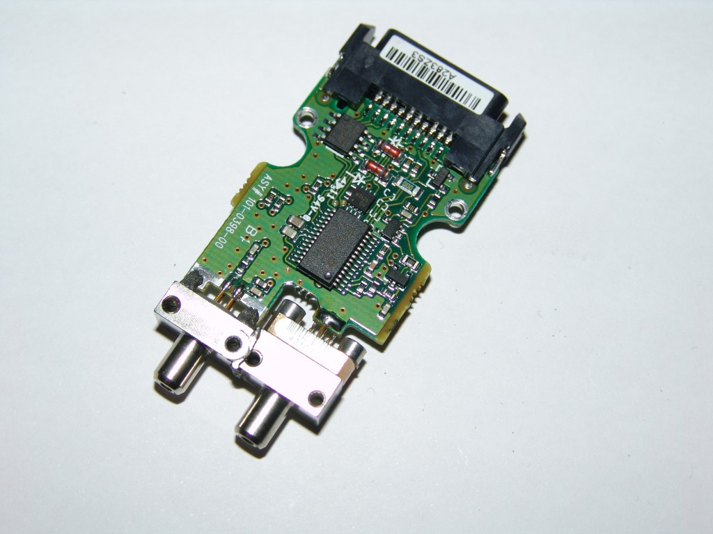
Fiber Optic Circuit
Source: Wikimedia Commons
Hence, the fiber circuit is a path where electrons travel with information and move to different electrical devices.
Also, it comes with a light that acts as the information carrier.
And this light spreads with the help of the total internal reflection via a transparent optical waveguide.
Hence, the cable takes the sound into the socket in the wall as you speak into the device.
Plus, it has no behavioral deficits.
Consequently, another line will move the sound to the local telephone exchange and probably face an initial overload failure.
But, the cellphone, on the other hand, works differently.
The device works by transmitting and receiving information with invincible radio waves and large-scale neural dynamics.
So, this happens because cell phones don’t use cables.
Types of Optical Fibers
Now that you know a bit about fiber optics, it’s crucial to understand that they transmit signals in different modes with additional safeguards.
The method refers to how a light beam passes down the fiber.
So, the signals may bounce down the fiber at different angles, go straight down to the fiber’s middle, or bounce the thread down at a low angle.
That said, we have two major types of fiber optic cables:
Single-mode Fiber
This fiber has a small diameter of the glass fiber core. So, it’s ideal for long distances.
The small diameter also reduces the chances of signal strength reduction.
Further, the single-mode fiber’s small opening helps to separate light into a single beam. Consequently, the cable provides a more direct route.
The single-mode fiber uses a laser light source, and it has a high bandwidth.
Also, this fiber requires an exact calculation to generate the laser light in its small opening, which makes it more expensive.
Multimode Fiber
The multimode fiber is the opposite of the single-mode fiber. It has a large core opening that permits light signals to bounce and reflect as they travel down the fiber.
Thanks to its large diameter, the fiber can send multiple light pulses down the cable at once, enabling more data transmission.
Also, it means that you may experience signal loss and interference.
Plus, multimode fiber uses an LED to generate a light impulse and is cheaper than single-mode fiber.
How Does the Fiber Circuit Work?
The fiber circuit moves information in photons or light particles that vibrate through a fiber optic cable.
That said, it’s vital to note that the cladding and glass core fiber have different refractive indexes.
Hence, the core and cladding bend the incoming light at a particular angle.
So, when the light signals move down the fiber optic, they experience total internal reflection. A comprehensive internal review happens when light signals reflect off the core (the central part of the cable) and cladding (a layer of glass that wraps around the outer part of the core).
And this usually happens in a sequence of zig-zag bounces.
Also, the total internal reflection is one of the things that ensure that light remains in the pipe.
However, due to the denser glass layers, the signals tend to travel 30% slower than the speed of light.
Also, use repeaters at distant intervals if you want to boost the signal throughout its journey.
Why do you need repeaters?
They help to regenerate optical signals.
They do this by changing the visual signal to an electrical signal. Then, the repeater processes the electrical signal and retransmits it as optical.
Fiber Circuit: Applications
Fiber optics transmits data coded in a beam of the light modulator, which is useful for network modulation.
The information then moves down a pipe (plastic or glass). This design idea originated in the 1950s.
The idea was to couple efficiencies, endoscopes, and efficient grating couplers.
Also, it helped doctors view the human body internally, using multi-fiber photometry, without cutting it open.
Engineers liked the idea and used the same technology to move telephone calls at the speed of light.
Soon, the Federal Communications Commission (FCC) embraced the technology.
That said, the fiber optic cable consists of optical fibers (thin strands of plastic or glass).
Also, each of the fibers is relatively thin and can carry over 25,000 telephone calls.
Hence, the entire cable can transmit several million calls with ease.
In summary, fiber optic cables use light-based technology to move information between two places.

The Fiber Optic Circuit Design
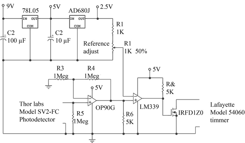
Fiber Optic Circuit Design
Source: Researchgate c/p Richard Cole
The circuit design has two significant parts we’ll discuss separately: the transmitter and receiver circuit.
Fiber Optic Transmitter Circuit
Here are the components you need to build a low-cost fiber optic transmitter circuit:
Battery
- Case
- SK1 3.5mm jack board
- Circuit board
Semiconductors
- D1 (LED)
- IC1 (NE555)
- IC2 (1458C)
- Tr1 (BC141)
Capacitors
- C1 (220m 10V elect)
- C2 (390pF ceramic plate)
- C3 (1u 63V elect)
- C4 (330p ceramic plate)
- C5 (4n7 polyester layer)
- C6 (3n3 polyester layer)
- C7 (470n polyester layer)
Resistors (all 1/4 watt, 5%)
- R1 (47R)
- R2 (4k7)
- R3 (47k)
- R4 (10k)
- R5 (10k)
- R6 (10k)
- R7 (100k)
- R8 (100k)
Since your IC1 is NE555, you should expect decent performance efficiency. You can also control the frequency by joining the input signal to the IC‘s pin 5.
The pin connects with the voltage divider. You need to configure your voltage divider to generate the NE555’s 2/3V+ and 1/3V+ switching limits.
Further, it’s vital to increase or decrease the upper limit. That way, you can increase or decrease the time that C2 takes to switch between the two ranges.
Since the TR1 offers the high drive current that illuminates D1 (LED) ideally, you must wire it like an emitter follower buffer stage.
Also, apart from the IC1 with a decent 200mA current for the D1, you need a separately controlled driver for your LED.
And this will help you get your preferred LED current precisely and reliably.
In addition, position the R1 to fix the LED current, which is about 40mA.
While you’re at it, note that the LED can only work with 50% (20mA) of its actual rating.
This happens because the LED switches ON/OFF at a rate of 50%.
Plus, you can adjust the R1 value when necessary—to increase or decrease the output current.
Fiber Optic Receiver Circuit
The components you need for the receiver circuit and filter are:
- Wire
- SK1 25-way D connector
- Circuit board
- Case
Semiconductors
- TR1, TR2 BC549 (2 off)
- D1
- IC1 (4001BE)
- IC2 (1458C)
- IC3 (CA3140E)
Capacitors
- C1 (100m 10V electrolytic)
- C2 (2n2 polyester)
- C3 (2n2 polyester)
- C4 (390p ceramic)
- C5 (1m 63V electrolytic)
- C6 (3n3 polyester)
- C7 (4n7 polyester)
- C8 (330pF ceramic)
- C9 (3n3 polyester)
- C10 (4n7 polyester)
Resistors
- R1 (22k)
- R2 (2M2)
- R3 (10k)
- R4 (470R)
- R5 (1M2)
- R6 (4k7)
- R7 (22k)
- R8 (47k)
- R9 (47k)
- R10 – R15 10k (6 off)
The fiber optic receiver is above the filter. The receiver’s output connects with the filter circuit’s input.
The D1 creates the detector diode, which functions in the reverse bias setting. Consequently, the leakage resistance forms an LDR effect.
R1, on the other hand, behaves like a load resistor.
Plus, the C2 links the detector stage and the input amplifier.
As a result, there will be a two-stage capacitively connected network.
And the two locations will work simultaneously in the common-emitter mode.
It’s possible to push the monostable multivibrator—If you provide an efficient high input voltage oscillation at the semiconductor (TR2).
It will permit a superior overall voltage gain (>80dB).
The filter stage is built around 1458C (a/b). It’s an 18 dB per octave (2/3rd order) filter system with details commonly used in transmitter circuits.
Pros of the Fiber Optic
- You can submerge fiber optics in water
- It can support high bandwidth capacities
- The cables are light, thin, and strong
- It doesn’t need a signal boost to allow light to travel further
- The fiber optic doesn’t need frequent maintenance or replacement
- Less prone to electromagnetic interference
Cons of the Fiber Optic
- It’s quite pricey
- Installation is labor-intensive
- The cables are fragile
- The glass fibers need more protection
Final Words
The fiber circuit plays a vital role in fiber optics as a whole.
Most people prefer fiber optic cables over copper cables.
And it’s no surprise considering that the former has benefits like high transmission speed, bandwidth, etc.
Plus, they work perfectly for high-performance data networking and long-distance.
What do you think about the fiber circuit?
Do you have questions or suggestions about the topic? Please feel free to reach us.


