
The fish stunner circuit diagram is a fish-catching device built with just a few simple components. It’s designed to kill fish by delivering an electric shock. This electric current shocks the fish and leaves the fish in an unconscious state. As a result, it makes it easy for you to catch them without any struggle whatsoever.
We can build a fish stunner circuit using common parts found at most electronics stores and in our homes.
This article will walk you through how to build your fish stunner circuit.
Let’s get down to it!
Contents
What is a Fish Stunner Circuit?
A fish stunner circuit is an electric fishing machine that uses high voltage to quickly and humanely kill fish. It is also called an electric fish shocker circuit. While its name might sound scary, this device will only immobilize the fish.
So, it eases your work as you can always catch fish without struggling or causing unnecessary pain for the fish.

(a photo of a school of tuna fish in the ocean.)
How is it Working
Working principle of a fish stunner circuit
The fish stunner circuit works by converting the current in a 12v battery to an alternating current of 220v.
For a better understanding of explanations, you can always refer to the circuit diagram below.
First, the transistor directly at the top will be the first to conduct current. Then, the center trap OV will receive the output current from the 12v battery that will flow to the terminal.

(Abstract Electric Shock Effect)
Next, this voltage will make the center point its positive voltage. Meanwhile, the negative voltage will be at the upper point and the other 12v terminal.
During this time, the lead B of the above transistors should have a bias current. When these transistors don’t conduct the current, it loses the magnetic field around them. As a result, this causes a negatively reverse-phase induction center.
We should know that the positive terminal is the 12v. Nevertheless, the bias of lead B of the below transistors Q1 and Q2 occur when the positive voltage flows to R.
Consequently, this results in a connection by the switches. Also, an electromagnetic induction to the coil of the lower switch from the 12v occurs.

(Transistors and microchips on a circuit board.)
Circuit diagram introduction of a fish stunner circuit

(Fish Stunner Circuit Diagram.)
We use a soldering iron at open-air and an AC light with an electrical current of 220v AC. Also, we require a 150watt AC circuit mini-inverter as part of the components.
Since we only require a 30W-simple inverter for a short time, we do not need high power. Then, we look for numerous MJ2955 control transistors.
Significantly enough, we need the connection in an astable multivibrator shape with two MJ2955, two 68-ohm resistors, and a transformer. The transformer occasionally acts as the load that converts electrical current into high voltage in the case of a 220V system.
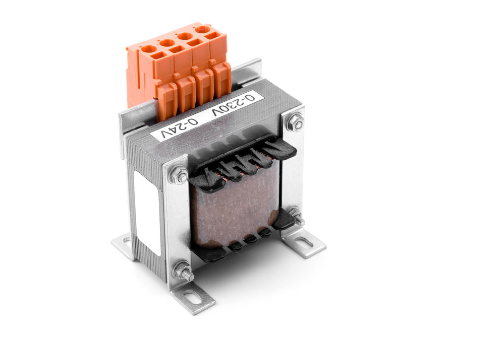
(example of a transformer.)

How to Build a Fish Stunner Circuit
Components needed
We might need more components to build a fish stunner circuit. However, in this article, we are learning how to make a straightforward electric fish shocker. So, the details listed below are all we need to start the circuit building.
- One 12-0-12 volts
- One 3A power transformer.
- A 2N3055 transistor or transistor D313.
- A heat sink
- 1N4007 diode
- R-470ohms
- Inverter board.
- Connecting wires.
- 0.1uF capacitor
- Ferrite core EE55
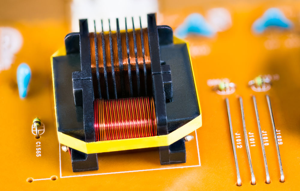
(Magnetic ferrite core transformer.)
Simple build steps to follow
First, we connect 12-0-12 volts to a transformer output of about 3A. Next, screw a 2N3055 or a transistor D313 transistor to a large heat sink. Not to forget the R-470 ohms, 0.1uFcapacitor, and the 1N4007, which we should connect as shown in the diagram above.
At this point, you should use an inverter board and join the power output to the input. Then, connect the output to wires and finally into the prongs to shock the fish.
Above all, the intensity of current flows from the second terminal determines the chances of shocking the fish and the number of fish surprised in your application.
Moreover, you should know that the possibility of the beauty shocking you is zero to none, and this is because it’s not an entire circuit unless you complete the course by touching both of its ends.
(Fish illustration icon)
Summary
We’ve talked about the fish stunner circuit. Moreover, we hope you we’ve learned about how the fish stunner circuit works in this post. Now, to you, happy building!
If you feel lost or want to ask for help at any point, please get in touch with us. Our team members are always available for questions and would love to hear from you.


