Contents
How Does a Flame Sensor Work?
Flame sensors can save you from severe accidents like catastrophic explosions. However, in hazardous areas, failure to detect fire outbreaks could wreak havoc on your equipment.
Heat can damage flame sensors quickly, so it’s best to install them a distance away from the potential fire source. However, this doesn’t decrease their effectiveness. In short, flame sensors are so light-sensitive that they can detect flames from a 100 cm distance with a detection angle of 600.
Also, some flame sensors detect flame wavelengths within a range of 760 nm to 1100 nm, while others can only operate within a maximum of 300 nm wavelengths.
Hence, every flame sensor works differently, so let’s look at how each works.
Ultraviolet Flame Sensors
An ultraviolet flame sensor works within a maximum wavelength of 300 nm. These sensors measure the level of radiation in the air to detect flames or explosions within 3 – 4 milliseconds. A fire outbreak or explosion also releases extra radiation during ignition, which the sensor measures.
Infrared Flame Sensors
As the name implies, infrared flame sensors work only within the infrared spectral band. If there’s a flame, certain hot gases will generate patterns in the Infrared region.
Hence, the infrared flame sensor will analyze these patterns using a special thermal imaging camera. Thus, the entire process allows infrared flame sensors to detect explosions or flames.
Near IR Array Flame Sensors
Also called visual flame sensors, the near IR array flame sensors have advanced flame detection technology.
The sensor uses a pixel array of a CCD to read near IR radiation and detect the presence of flames.
IR3 Flame Detection Sensors
Unlike the near IR array flame sensor, this flame sensor does not measure background rotation. Instead, it measures the modulated elements of radiation.
Thus, IR3 Flame sensors have more precise flame detection.
Moreover, these are only some of the types of flame sensors. Other types include ionization current flame sensors and thermocouple flame sensors. You can find thermocouple sensors in heating systems and gas-powered ovens. At the same time, ionization flame sensors work for industrial gas heaters.
Flame Sensor Arduino
In truth, you don’t need to build your flame sensors from scratch. You can always order one for your projects. Hence, this section will discuss how to interface your flame sensor with an Arduino.
So, here are the materials you’ll need for this project:
- Flame sensor (preferably one with an analog out)
- Any source of flames for testing
- Arduino board
- Male-to-female jumper wires
Steps
Here are the steps you need to carry out this project successfully.
Step 1: Know the Type of Flame Sensors You Have
Before starting this project, you must understand your flame sensor products.
Hence, we recommend using this project’s flame detector with an analog-out feature. It should also work for short-range fire sensing–usually up to 3 feet. The flame sensors should monitor projects and cut devices off when they detect a fire.
- High sensitivity to IR wavelength at about 760 nm – 1100 nm light.
- It should have a real-time output voltage signal on its thermal resistance for its analog output (AO). Here are some other specifications:
- Its digital output (DO) should be a high-low signal generated when the temperature reaches the set limit. Also, you should be able to adjust the limit with a potentiometer.
Pins:
- Analog output (AO) pin
- Digital output (DO) pin
- Positive voltage input (VCC) pin (3.3 volts for digital and 5 volts for analog)
- Ground (GND) pin
Step 2: Test and Troubleshoot Your Sensor
Check if your sensor works before connecting it to your Arduino. To do this, you require a flame light source for testing.
First, connect your VCC to a power source (5v) and Ground pin. Next, close your flame source to the sensors, preferably within one foot. It should light up the digital output LED.
Now, don’t worry if the DO-LED fails to light up. Check whether you have a 5v power source or the flame is within range. You can also check if you connected the ground pin. Still not working? Then you have a faulty sensor.
Step 3: Wiring
Here, we need to wire the flame sensor to the Arduino. To achieve this, connect the flame sensors to the Arduino. Then, click the sensor’s pins to the Arduino’s pins. Hence, connect the VCC to the 5v pin, GND to GND, and AO to analog in 0.
Step 4: Arduino Code
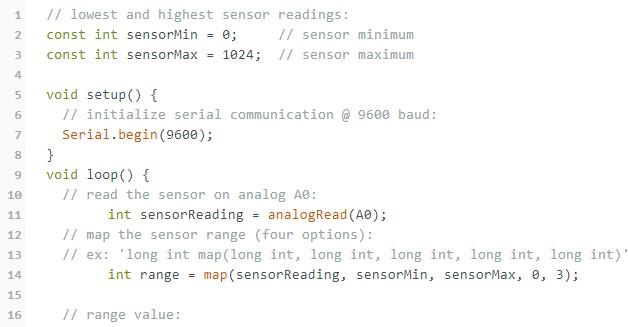
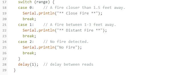
Indeed, the Arduino code will map and read the analog values the flame sensor generates. The values can be anywhere from 0 – 1024. Using this code will make the flame sensor react in the following way:
When you hold the flame within 1.5 feet of the sensor, it will activate “case 0,” and it’ll send “**Close Fire**” to the serial monitor. If you hold the flame within 1.5 feet to 3 feet of the sensor, it’ll activate “case 1″ and send “**Distant Fire**” to the serial monitor. Additionally, if it doesn’t detect any flame, it’ll activate “case 2” and send “No fire” to the serial monitor.
The best part is that the code constantly updates, so you can always get real-time feedback from the flame sensor. Here’s the code:
Flame Sensor Replacement
Like every other electrical device, Flame sensors can wear out over time and fail to get accurate flame detections.
The truth is that replacing a flame sensor for your circuits or devices is easy. You’d need to take different actions if you’re replacing the furnace sensor; buy another flame sensor and repeat the steps above to set it up. After purchasing your replacement flame sensors, open the access cover of your furnace and remove your old flame sensors. Afterward, install the new flame sensor and ensure everything is connected correctly.
Additionally, ensure the replacement is compatible with your circuit or furnace to avoid wasting time and money.

Flame Sensor Troubleshooting
If your flame sensors don’t work correctly, you can easily carry out a little troubleshooting. For your stock flame sensors, you can follow the troubleshooting steps we mentioned above. However, if you have furnace flame sensors, you can clean the soot on the sensor’s tip if it’s dirty or service it if the information is black.
When Should You Replace Your Flame Sensor?
It’s unsafe to wait for your worn-out flame sensors to misbehave before changing them. Failure to detect a flame early could cause many disasters. So, you should regularly maintain your flame sensors and replace them periodically. In short, flame sensors can last up to five years. But we recommend that you return them within two years for better performance.
Final Thoughts
A Flame sensor is an important safety device for gas-powered or heating applications, which are more prone to fire accidents and explosions. Flame sensors can help detect unforeseen circumstances.
Furnace sensors are different from stock flame sensors, so be sure to get the sensor that matches your project. The type of flame sensors you’ll need depends on your application.
Do you have any questions about flame sensors? If so, be sure to contact us, and we’ll be happy to help.


