Contents
What Are the Different Types of Soldering in PCB Assembly?

Choosing the right type of soldering can be challenging, but it’s crucial for proper assembly. Here are the three most common soldering techniques:
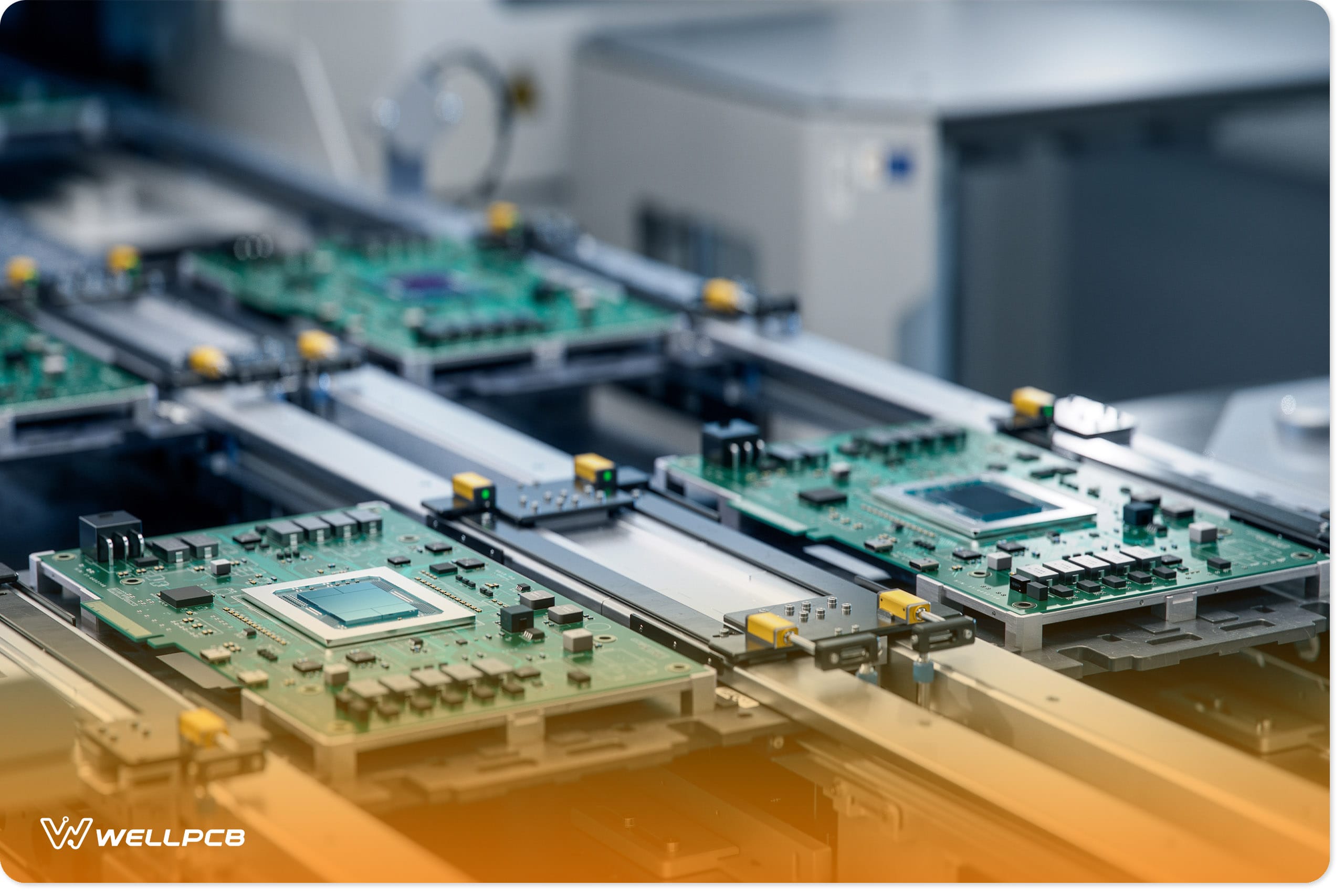
Reflow Soldering
Reflow soldering is widely used for high-volume and high-precision PCB assembly. In this method, the solder paste is applied to the PCB contact pads, and then surface-mount components are placed so their leads align with the paste. The PCB is then heated in a reflow oven, where the flux activates and the solder melts, forming solder joints. The solder joints then harden as they cool.
Reflow soldering is a practical choice for:
- High-volume PCB and device production
- High-density component soldering
- Compact and dense PCB assembly
- Integrating SMDs on PCBs
Reflow soldering provides several key advantages. By using less solder material and requiring lower heat, it is notably more energy-efficient than other methods. This process also reduces the risk of defects, such as cold solder joints, while significantly enhancing the overall quality of solder joints.
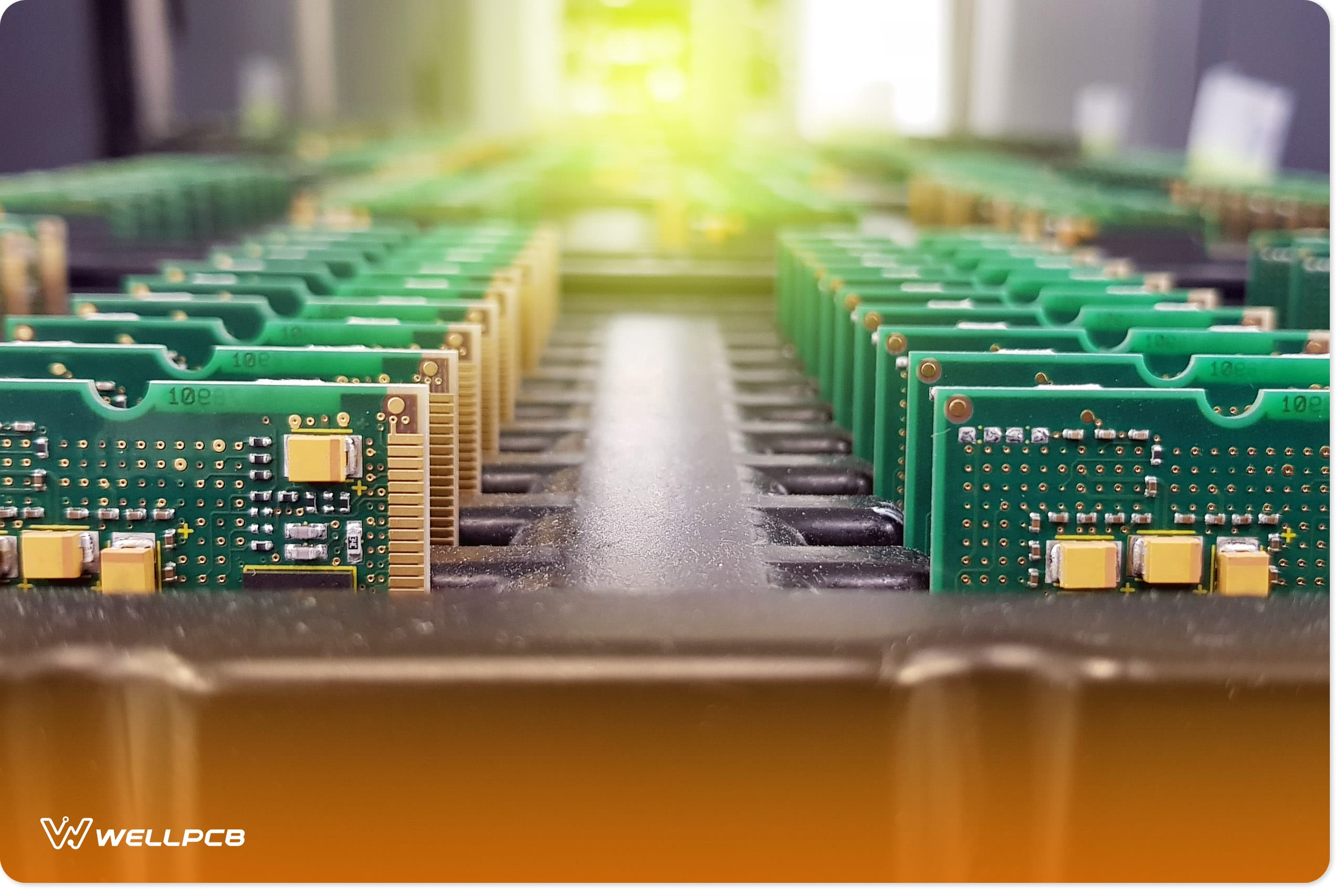
Wave Soldering
Wave soldering is a large-scale process used to solder electronic components onto a printed circuit board (PCB), creating a complete electronic assembly. The process involves four key steps.
- Flux is applied to the PCB surface to ensure cleanliness and proper adhesion.
The PCB is heated to activate the flux. - The board passes through a wave of molten solder, which coats the metal surfaces and connects the PCB components.
- The solder joints are cooled to harden, securing the components in place.
- Finally, excess solder or residue is removed to ensure a clean and functional board.
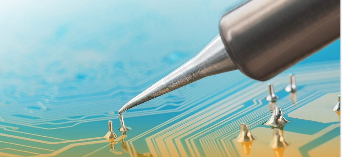
Manual Soldering
Manual soldering is ideal for prototyping, circuit rework, or repairs. Manufacturers and hobbyists use this method to attach components to PCBs, often in cases where parts are already mounted or when precision is required.
Key manual soldering skills include:
- Tinning: Coating the soldering iron tip with a thin layer of solder to enhance heat transfer.
- Heat application: Applying the right amount of heat to ensure smooth solder flow and strong joints.
- Proper technique: Using the correct soldering technique to create durable and reliable connections.
This method allows for flexibility and precision, making it a favored choice for small-scale tasks and intricate repairs.

How to Choose the Right Solder for Your PCB Assembly
Selecting the right solder material is vital, as it determines the strength of your solder joints. Each material has unique properties suited to different applications.
Lead vs. Lead-Free Solder
- Lead alloy solder: Lead alloy solder consists of 60% tin and 40% lead, melting at 183°C. Its excellent flow properties make it easier to work with, forming rigid solder joints. However, it is unsuitable for high-temperature applications and can lead to delamination, connection failures, component detachment, and short circuits.
- Lead-free solder: Lead-free solder, typically made of tin, copper, and other metals, is ideal for high-temperature environments. It forms stronger, more durable joints but has a higher melting point (217°C–220°C). Achieving clean solder joints can be more challenging due to wetting and solder flow issues.
- Silver alloy solder: Silver alloy solder is a reliable choice for projects requiring high-temperature performance. It nearly matches lead solder’s melting point, making it a practical alternative. Additionally, it bonds different metals effectively and fills fine gaps using surface tension effects.
Solder Wire Sizes
The ideal diameter of the solder wire will depend on the project. For instance, small components or densely packed PCBs typically require a wire diameter of 0.5mm to 0.8mm. General electronics work, such as soldering through-hole components, often uses solder wire ranging from 0.8mm to 1.2mm. Larger components benefit from solder wire with a diameter of 1.2mm to 1.6mm.
What Are the Essential Tools for PCB Soldering?

PCB soldering requires specific tools to ensure precision and efficiency. These tools streamline the soldering process, from application to cleaning.
Soldering Iron
Different types of soldering irons are available, each suited for specific needs:
- Standard soldering irons are ideal for hobbyists working on basic projects or repairs.
- Cordless soldering irons are battery-powered, offering portability for remote work.
- Temperature-controlled soldering irons allow precise temperature adjustments, making them perfect for soldering-sensitive components.
When choosing a soldering iron, consider which features are best suited for your application. For example, temperature control is ideal for soldering precisely without damaging components. Quick heating, on the other hand, is faster and more efficient.
Additional Tools
- Soldering stations: These multifunctional setups combine a soldering iron, power supply, and other tools, making them indispensable for PCB assembly. They are widely used by manufacturers and hobbyists for their versatility.
- Soldering iron tip: Made of copper with an iron coating, these tips efficiently transfer heat and resist corrosion for extended durability. Tip compatibility depends on the soldering iron’s brand and model. Common types include conical tips for small components and chisel tips for larger ones.
- Cleaning tools: Brass sponges or traditional sponges are essential for cleaning soldering iron tips, preventing oxidation and ensuring consistent performance.
- Solder sucker (desoldering pump): This tool removes excess solder from the board, a critical step for ensuring project success. Without it, excess solder can compromise the circuit.
Maintenance Tips
Proper maintenance of soldering tools is vital for longevity and performance. Regularly inspecting for wear and tear, cleaning tips, and addressing damage promptly will ensure the tools remain safe and effective.
What Are the Steps of PCB Soldering?

Soldering a PCB requires a systematic approach for reliable and precise results. Follow these steps to ensure a smooth process:
Preparation
- Clean the workspace: Use compressed air or isopropyl alcohol to remove dust and dirt. A clean surface prevents short circuits, extends component life, and ensures good connections.
- Use a static mat: This will protect your PCB from static electricity, which can damage components.
- Gather tools: Prepare a soldering iron, stand, solder, flux, safety glasses, and a multimeter. Proper preparation saves time and ensures efficiency.
The Soldering Process
- Warm the iron
Preheat the soldering iron by setting it to the desired temperature. Allow it to warm up for five to ten minutes until the indicator light turns off or changes color, signaling it has reached the appropriate temperature. This will ensure the solder melts properly.
- Tin the tip
Before soldering, cover the tip of the iron with a thin layer of solder. This step, known as tinning, prevents oxidation and improves heat transfer. After tinning, wipe off excess solder using a damp cloth. The tip should appear shiny and clean. Any excess solder risks damaging components, creating messy solder joints, and reducing heat transfer.
- Apply the solder
Begin by soldering one or two components at a time for simple circuits. For complex PCBs, solder the small components before the large ones. Place small components in their designated positions on the board. For through-hole components, bend the leads slightly to hold them in place.
Hold the soldering iron so that the tip touches both the component lead and the PCB pad. This ensures efficient heat transfer for proper solder flow. Avoid overheating the joint. If the solder starts bubbling, remove the heat and let the joint cool before reheating.
Use the soldering iron tip to touch the component lead and pad, applying the solder on the joint. If you have heated this space as required, the solder should flow freely while the flux bubbles.
Add sufficient solder to form a slight, hollow curve around the joint. Don’t move the PCB once the solder flows into the joint, as this can result in a dull, grainy solder joint finish.
Post-Soldering
Once the solder cools, inspect the joints carefully. If they appear smooth, use wire cutters to trim the excess leads. Once satisfied, use isopropyl alcohol and a microfiber cloth to remove extra flux residue from the board, leaving a clean finish.
Common Soldering Issues and Solutions

Improper soldering techniques or incorrect temperature settings can lead to various problems, affecting performance and circuit lifespan. Here are a few common issues and their solutions:
Cold Solder Joints
Cold solder joints occur when the joint is not heated sufficiently. These joints have a dull, grainy finish compared to proper solder joints, and may show incomplete solder coverage on component leads.
To fix this, reheat the joint using a hot soldering iron until the solder melts smoothly. Adding new flux can improve bonding further. Another option is to remove the old solder entirely and resold the joint.
Excessive Solder and Solder Balling
Using too much solder creates solder balls or oversized joints, which degrades long-term PCB performance.
To prevent these issues:
- Store PCBs in a dry area and bake them before soldering to remove moisture.
- Apply solder paste evenly in the correct amount.
- Use a vacuum desoldering pump or solder wick to remove excess solder or balls.
- Apply flux to the area to aid in removing unwanted solder.
- Clean the PCB afterward to eliminate loose solder.
Always remember to set the proper solder and preheating temperature, change flux, and clean solder dross regularly.
Insufficient Wetting
Insufficient wetting happens when solder does not flow evenly over the joint, leading to poor connections and performance issues in the PCB. Common causes include contamination, insufficient flux, and joint surface oxidation.
To prevent insufficient wetting:
- Set the soldering iron to the correct temperature
- Apply heat evenly to the pad and component leads
- Cleaning the workstation
- Use high-quality flux
Safety Precautions in Soldering
Safety is essential during soldering to prevent injuries and component damage. Follow these guidelines to work safely and efficiently:
Temperature Handling
Soldering involves high temperatures that can burn skin and damage components. To minimize risks, don’t place the iron on the joint for longer than three seconds. It’s also important to wear heat-resistant gloves and safety glasses to protect against accidental burns.
Fume Management
Soldering emits harmful fumes that should not be inhaled. To protect yourself, wear a respirator designed for soldering fumes — a dust mask is adequate. It’s also important to ensure proper ventilation by working near an open window or using a fan to redirect fumes away from your face. Safety glasses and gloves will keep your eyes and hands protected, too.
Tool Safety
Always inspect soldering tools for damage before use. This will prevent component damage and ensure the process runs smoothly. When finished, store the equipment in a safe place away from any children and pets, such as a locked drawer or a toolbox.
Conclusion
Soldering is a crucial step in PCB assembly. As noted, it’s important to use the right tools, techniques, and materials for the project. Inspect tools regularly to maintain safety and prevent issues like cold solder joints, solder balling, and insufficient wetting.
Always follow best practices and prioritize safety when soldering PCB components to avoid injuries or health risks like burns or fume inhalation. This means wearing the right protective gear, including a respirator, gloves, and safety glasses. By following these guidelines, you’ll finish the project efficiently without harm to yourself or your PCB.
Stay informed and up-to-date with the latest tips, techniques, and industry insights by visiting the WellPCB blog regularly. For expert support on your next project, contact us today.