Electronic oscillators are electronic circuits that convert DC power to an AC signal. Depending on the type of frequency selective filter, you can group them into RC oscillators or LC oscillators.
One of the most common oscillators that you’ll find in radio receivers or as RF oscillators is the Hartley Oscillators. It’s an advancement from the Armstrong oscillator, and it’s easy to tune. Today, we will dive deeper into its operation, configurations, etc., as we move along the article.

An electronic oscillator
Source; Wikipedia
Contents
- 1 What are Hartley Oscillators?
- 2 Working Principle and Circuit Diagram of Hartley Oscillator
- 3 Oscillation Frequency of the Hartley oscillator
- 4 Hartley Oscillator in Different Configurations
- 5 Hartley Oscillator Using Op-amp (operational amplifier)
- 6 Advantages and Disadvantages of Hartley Oscillator
- 7 Conclusion
What are Hartley Oscillators?
Hartley oscillator, an invention by Ralph Hartley in 1915, is a type of harmonic oscillator. An LC oscillator (a circuit with inductors and capacitors) determines its oscillation frequency. You can tune them to generate waves in a radiofrequency band, hence known as RF oscillators. The RF range of the sine wave signal starts from 30kHz to 30MHz.
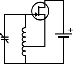
Simple Hartley oscillator
Source: Wikimedia
A feature that distinguishes the oscillator’s the tuned circuit having one capacitor in parallel connection with two single tapped inductors. What’s more, it takes the feedback signal required for oscillation from the inductor’s center connection.
Working Principle and Circuit Diagram of Hartley Oscillator
A Hartley oscillator has several circuit components as in the diagram with different functions.
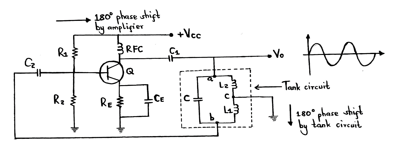
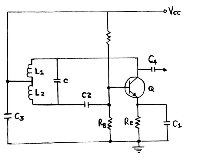
A Hartley Oscillator circuit diagram
R1, R2, and RE provide the required circuit biasing while C2 and C1 function as the coupling capacitors.
Then, the radio frequency choke coil (RFC) separately maintains the conditions of DC and AC in the circuit. It’s because it shows nearly zero reactance in DC conditions, thus not causing disruptions in DC capacitors. Further, RFC reactance in high-frequency applications is large, so you can consider it open-circuited.
The circuit also has a transistor amplifier that provides a phase shift of 180°. L1, L2, and C, components of the tank circuit, generate the oscillating frequency.
Now, in terms of the working principle;
- If you apply DC supply voltage (VCC) to the circuit, there will be an increase in the transistor’s collector current. That’ll start charging the capacitor in the tank circuit.
- After a full charge, the capacitor will start discharging through L2 and L1 inductors.
- As the capacitor discharges, the inductor will start charging.
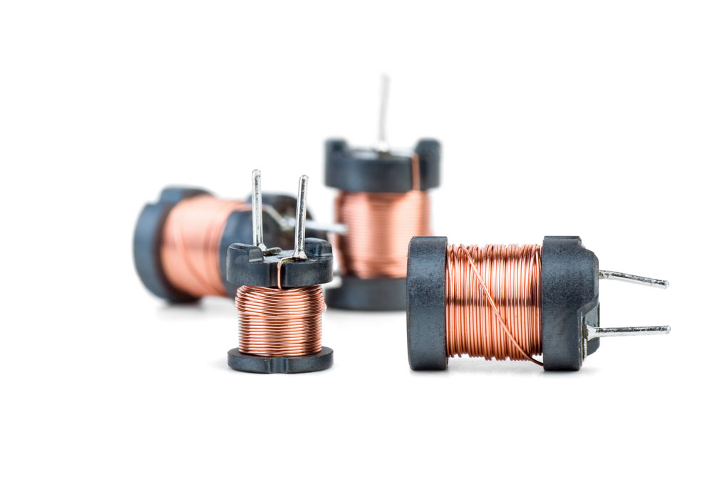
(inductor coils)
Note;
A capacitor stores charge in an electric field, while an inductor stores in the form of a magnetic field. Therefore, when a capacitor fully discharges, the inductor will automatically start charging and vice-versa.
- The continuous discharging and charging leads to the output having sinusoidal oscillations. And since our amplitude is also gradually decreasing, we’ll majorly have damped oscillations at the output signal. The amplitude decrease is due to the inductor’s internal resistance that results in heat loss in the circuit (I2R).
- Moreover, the tank circuit provides a 180° phase shift between points B and A. Point C, however, remains grounded. As such, when b is negative, a will be positive.
- To sustain our oscillations for a long time, we’ll need to amplify our damped sinusoidal oscillations. And so, we’ll provide the tank circuit’s output as input to a transistor with a common emitter configuration. There, the transistor will amplify the sinusoidal signal.
- Next, the mutual inductance amid inductors L1 and L2 receives the feedback signal/energy.
- Afterward, the capacitor in the tank circuits further produces sinusoidal oscillations after receiving charging energy from transistors with amplified output.
- In another sense, the amplified output compensates for heat losses the tank circuit incurred. Therefore, the tank circuit ensures a constant output amplitude over a working frequency range instead of decreasing amplitude.
Oscillation Frequency of the Hartley oscillator
You can calculate the frequency of oscillations that a tank circuit produces similarly to any parallel resonant circuit. For that, we’ll use the formula;

C is the capacitance of C1 in the tank circuit.
In Hartley oscillators, we use two inductors in the tank circuit. So, our equivalent inductance will be;
Leq = L1+ L2
We must also consider the mutual inductance between the coils when finding the equivalent inductance. It’ll be;
Leq = L1+ L2+ 2M
Finally, we’ll collate the oscillating frequency as;


Hartley Oscillator in Different Configurations
Shunt-fed Hartley Oscillator
A shunt-fed Hartley oscillator uses a common-emitter configuration.

A shunt-fed Hartley oscillator
When using one supply voltage, the voltage dividing resistors RB and R1 supply the fixed bias.
C1 bypasses RE, the emitter-swamping resistor that stabilizes the temperature.
Then, inductor L3 shunt-feeds the collector as C3 functions as a coupling capacitor and DC blocking. The blocking and coupling prevent the collector from short-circuiting.
Likewise, C2 is the base-blocking coupling capacitor that ensures the base to the ground has no short circuits.
Operation of a shunt-fed Hartley oscillator
After the shunt-fed circuit receives some energy, R1 and RB determine the initial bias. At the same time, feedback gotten from the collector to the base via L2 and L1 builds up an oscillation.
Note;
An AC path exists from the emitter through L2 and C2 to the base. The path is similar to the one via L1 and C3 to the collector.
A degenerative bias develops crossway RE during oscillation (and a correct value of C1).
Shunt-led element values determine the following:
- RB and R1 values provide class C bias for an easy startup.
- The C1 and RE values are for temperature stabilization.
- Last, class C or B bias values determine the required efficiency of operation.
The output can finally come from an inductor to the tank or the capacitor to the collector.
Series-fed Hartley Oscillator
In our second configuration, the series-fed Hartley oscillator, the base circuit is also emitter-stabilized and voltage-divider biased. As you apply the collector voltage through the tank inductor tap, C3 shunts the voltage source for the signal. Further, its operation is similar to the shunt-fed circuit.
The difference comes when the DC flows through a section of the tank circuit. Here, the Q factor and oscillator frequency stability become lower than a shunt-fed circuit.
Circuit diagram of a series-fed Hartley oscillator
Hartley Oscillator Using Op-amp (operational amplifier)
One major advantage of the op-amp is, you can individually adjust the oscillator’s gain using an input and feedback resistooscillator’s arrangement of the op-amp is in an inverting mode. Therefore, you can express the gain by using the equation;
A = -Rf/R1
Whereby;
-Rf = feedback resistor
R1 = input resistor
A = Gain
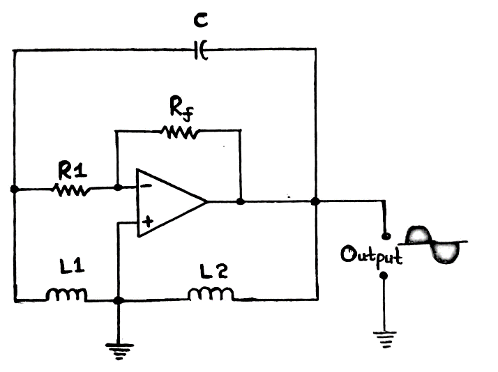
A Hartley oscillator using op-amp
In inversions with transistors, the gain will be slightly greater than or equal to the ratio of L2 and L1. In the Op-amp circuit version, increased frequency stability since it minimally depends on the tank circuit elements. But, both the transistor version and op-amp version have similar frequency equations and working principles.
Advantages and Disadvantages of Hartley Oscillator
The pros of a Hartley oscillator include;
- First of all, you can use a single coil as an auto-transformer instead of a large transformer.
- Secondly, you’ll only need a few components, such as two fixed inductors or a tapped coil.
- Furthermore, if you replace the capacitor with a quart-crystal, you can generate a variation of a fixed-frequency crystal oscillator.
A quart crystal
Source; Wikipedia
- Then, you’ll be able to maintain the output amplitude over the required fixed frequency range.
- Lastly, you can vary the frequency using a variable inductor or a single variable capacitor.
The cons are;
- Unfortunately, you can’t use Hartley oscillators for low-frequency oscillations.
- In addition, it has harmonic distortions therefore not suitable for applications that need pure sine waves. Luckily, you can remove the distortions by adding an amplitude-stabilization circuitry.
Conclusion
Briefly, Hartley oscillators have various applications, like producing a sine wave of the desired frequency. Not only that, but they also have many configurations such as Field Effect Transistor (FET) amplifier based, series-or shunt-fed, etc.
You can reach out to us for more knowledge on Hartley oscillators. We are at your service.


