Contents
- 1 Understanding the Oscilloscope
- 2 Proper Grounding
- 3 Setup
- 4 Calibrating the Instrument
- 5 Connecting the Probes
- 6 Compensating the Probes
- 7 Scale
- 8 Measuring Amplitude
- 9 Measuring Frequency
- 10 Advanced Oscilloscope: AC/DC/Ground Coupling
- 11 Advanced Oscilloscope: Dual Channel Measurements
- 12 Advanced Oscilloscope: X-Y Mode
- 13 Conclusion
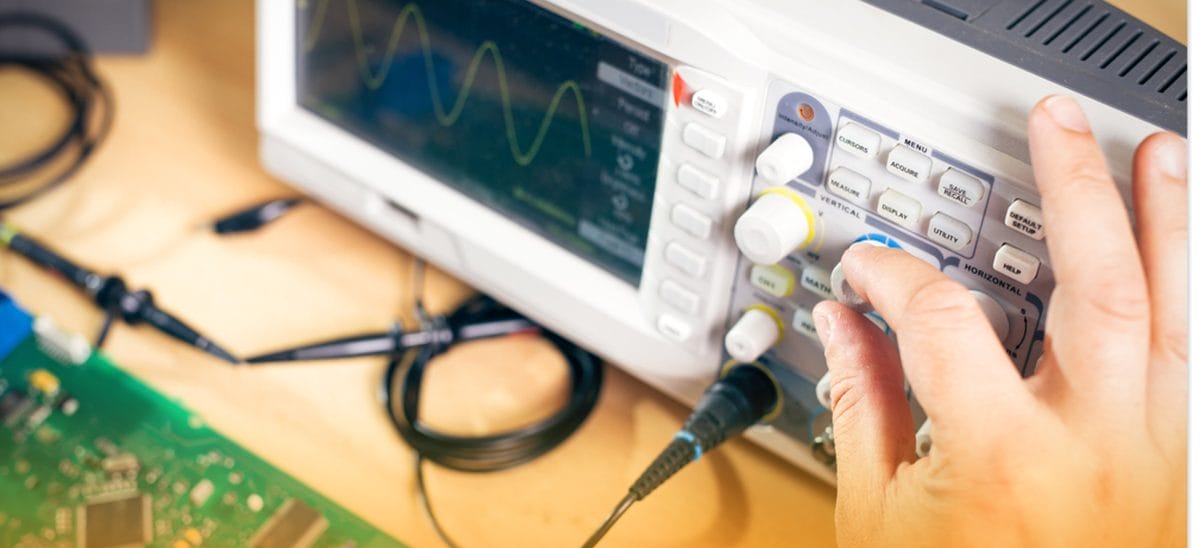
Understanding the Oscilloscope
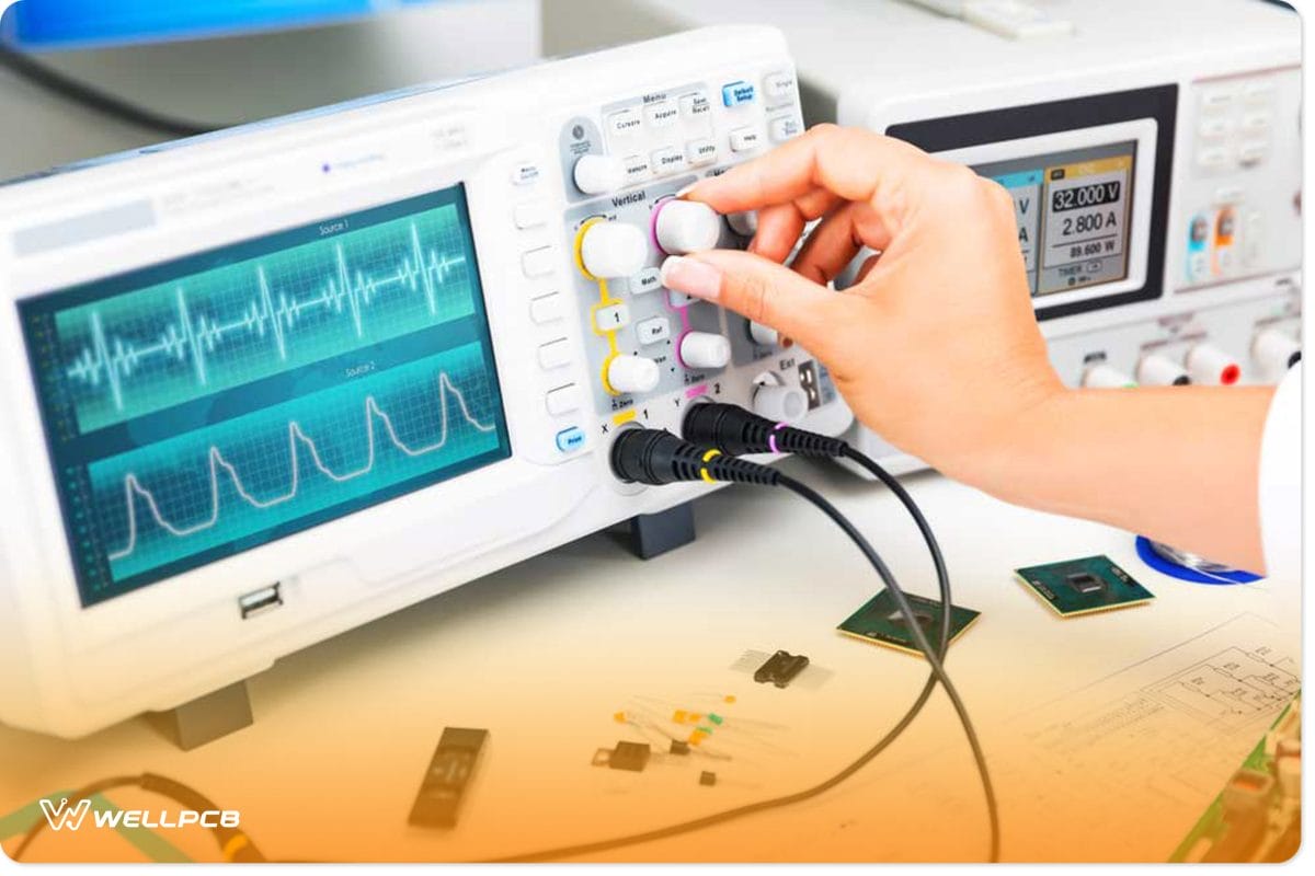
Fig 1: A digital oscilloscope
Oscilloscope Measures
An oscilloscope measures the voltage signal of an electrical current. And, unlike the multimeter, it plots multiple voltages as wave patterns, enabling you to study a voltage signal over time.
Explore the Display
- Voltage
The oscilloscope displays the voltage over time as a wave pattern.
- Frequency
The frequency is the rate per second at which a wave repeats itself.
- Wavelength
The wavelength is the distance between two identical points in adjacent waveform cycles.
- Slope Length
You can use an oscilloscope to measure the time it takes for a wave to rise to its peak and drop again.
Oscilloscope Channels
A majority of oscilloscopes have two to four channels. Each channel has an input you can connect the probe to, allowing you to measure multiple signals simultaneously.
The Difference Between Periodic and Non-Periodic Waves
Periodic waves have a consistent pattern that repeats itself at regular time intervals. Non-periodic tides change constantly and thus do not have a predictable way. They’re generally the result of external input, such as atmospheric interference or user input.
The Different Types of Waves
- Sine Waves
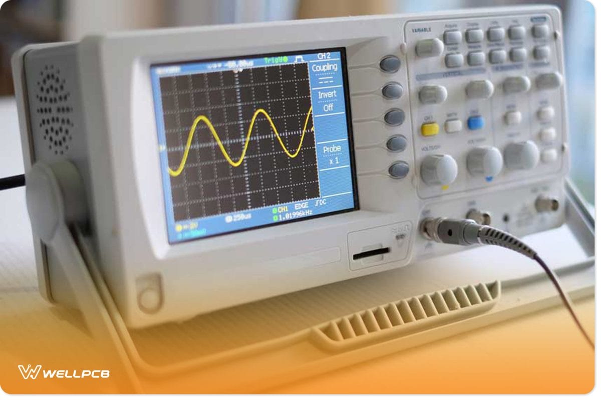
Fig 2: A sine wave on an oscilloscope display
A sine wave is a geometric waveform that consistently oscillates up and down. The function y = sin x defines it.
- Square Waves
A square wave is a non-sinusoidal periodic waveform whose amplitude rises suddenly when on and then drops to a minimum when off. It’s common in many time-based digital components.
- Triangle Waves
In triangular waves, the signal rises consistently up to a maximum and then drops to a minimum. The result is triangular-shaped waves. Other times, the movement increases but drops suddenly, resulting in triangular, sawtooth waves.
- Complex waves
Complex waves are non-periodic waveforms that contain any combination of the above signals.
Proper Grounding
Just like other electrical apparatus, grounding the oscilloscope is essential to:
- Protect its integrated circuits (ICs) from electrical damage
- Protect yourself from hazardous shock
Grounding or earthing is the process of providing an electrical path for a fault current to flow to the earth. Typically, the electrical current takes the shortest low resistance path in any electrical setup. If you fail to ground your oscilloscope, touching its metallic parts causes stray currents to pass through your body.
Secondly, grounding is vital to get accurate measurements with your oscilloscope. The oscilloscope must have the same ground as the circuit you’re testing. To ground it, plug its three-prong power cord into a rated power outlet that’s grounded.
However, some oscilloscopes have insulated cases and controls and do not need a separate connection to the Earth. For these, don’t waste time looking for the earthing cable.
Furthermore, please note that you must ground yourself when working with the ICs. They have small conduction paths that may get damaged by the static electricity on our bodies. Consequently, wear a grounding strap to discharge excess static electricity buildup.
Setup
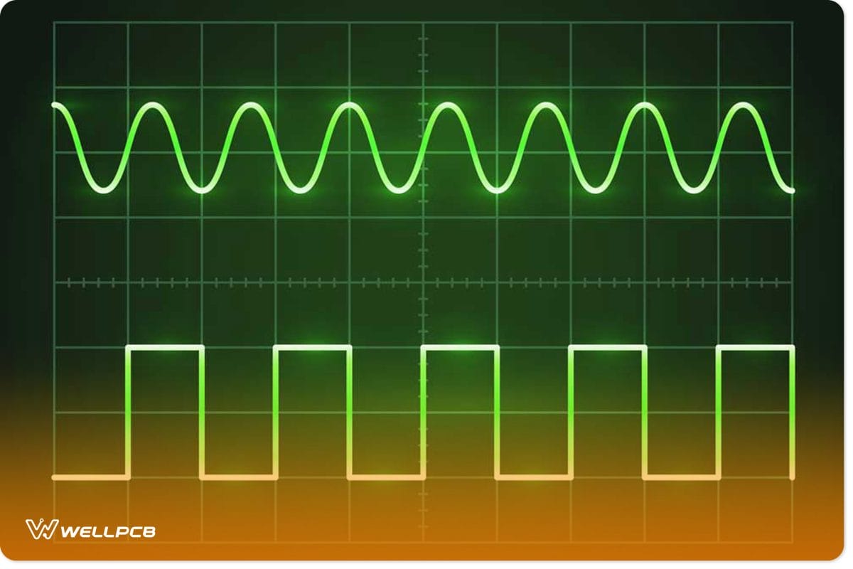
Fig 3: Sine and square waves on one oscilloscope display
Look at the oscilloscope’s front panel after plugging it in. You’ll notice that it’s divided into three sections: horizontal, vertical, and trigger. Some oscilloscopes may have more areas depending on the model and type.
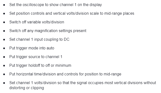
Next, look for the input connectors of the oscilloscope, as that’s where you’ll attach your probes. Some oscilloscopes may not have the DEFAULT and AUTO SET buttons. For these, set up the controls to standard positions first, and then you can take the measurements.
Here are the setup instructions:
Calibrating the Instrument
Electrical instruments may develop some errors after some time of use. It’s especially the case once the ambient temperature has deviated by more than 5° C (9° F) since the last self-calibration. Consequently, we recommend periodic recalibration for accurate measurements. As recalibration may differ with the oscilloscope, you should refer to the manual that comes with it before commencing.
Connecting the Probes
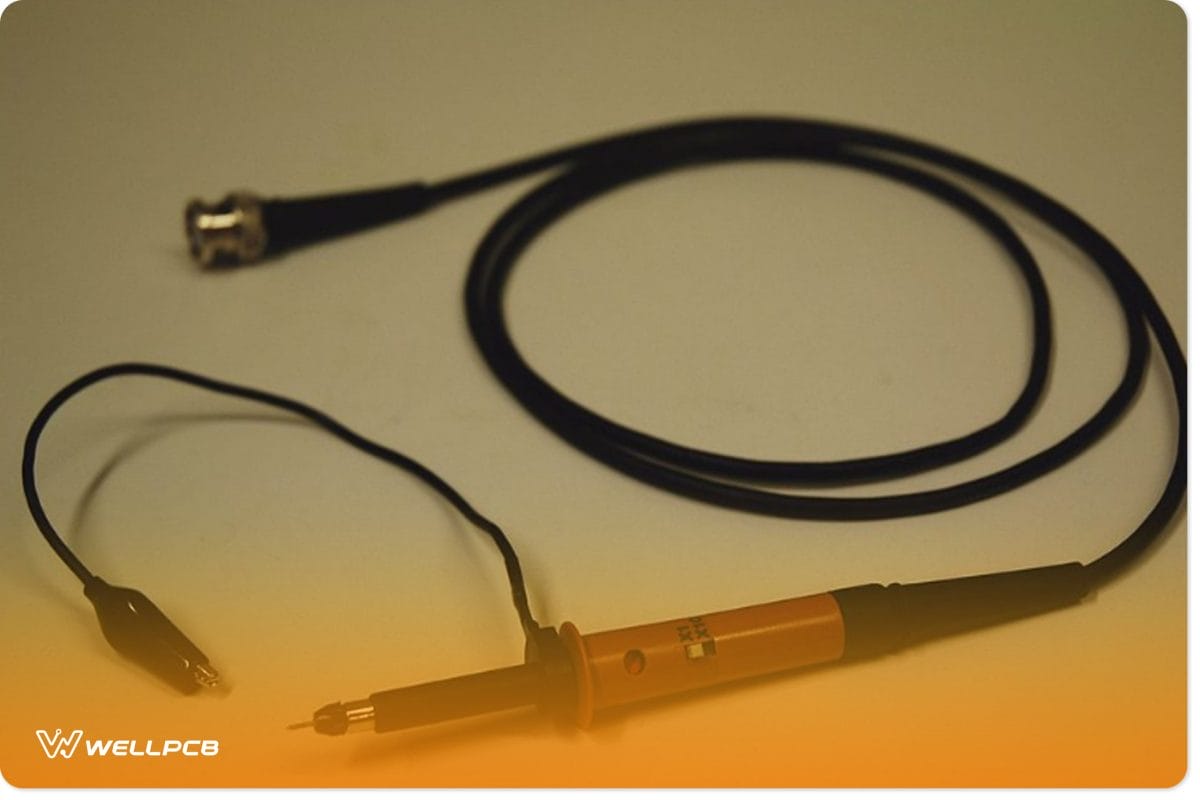
Fig 4: A passive oscilloscope probe
Source: Wikipedia
An ideal probe gives you access to all performance and power in the oscilloscope. Moreover, it ensures the maximum integrity of the signals you’re measuring. It would be best if you only connected the probes once you’ve grounded the oscilloscope and yourself.
To do so requires the probe tip and ground connections. Luckily, probes usually come with clip attachments for grounding the circuit you’re testing.
Compensating the Probes
Make it a habit to compensate a passive attenuation probe to an oscilloscope every time you set up a measurement. A poorly adjusted examination lowers an oscilloscope’s accuracy, leading to misleading results.
Many oscilloscopes have a square wave signal available at their front panel’s terminals for probe compensation. Here’s how to compensate for a probe:
- Connect the search to a vertical channel
- Attach the probe tip to the square wave reference signal or probe compensation
- Ground the probe’s ground clip
- Look at the square wave reference signal
- Adjust the movement so that the square wave corners are square
Scale
Here, adjust the time/div, volts/div, and vertical position until you see your full wave without clipping or distortions. For example, set your volts/div to 1V, time/div to 1ms, and vertically center the lock on your screen.
When setting the scale, there’s no definitive measurement to stick with for your project. Consequently, play around with the three controls until you get the best image.
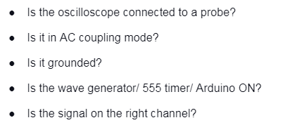
If not, ask yourself these questions.
Measuring Amplitude
A wave’s amplitude measures the distance between its equilibrium and the peaks. Suppose the distance between the equilibrium and the peaks is 2.5 vertical grid divisions. If the volts/div is 1 volts, 2.5 divisions equals 2.5 volts. Therefore, your wave’s amplitude is 2.5 volts.
Measuring Frequency
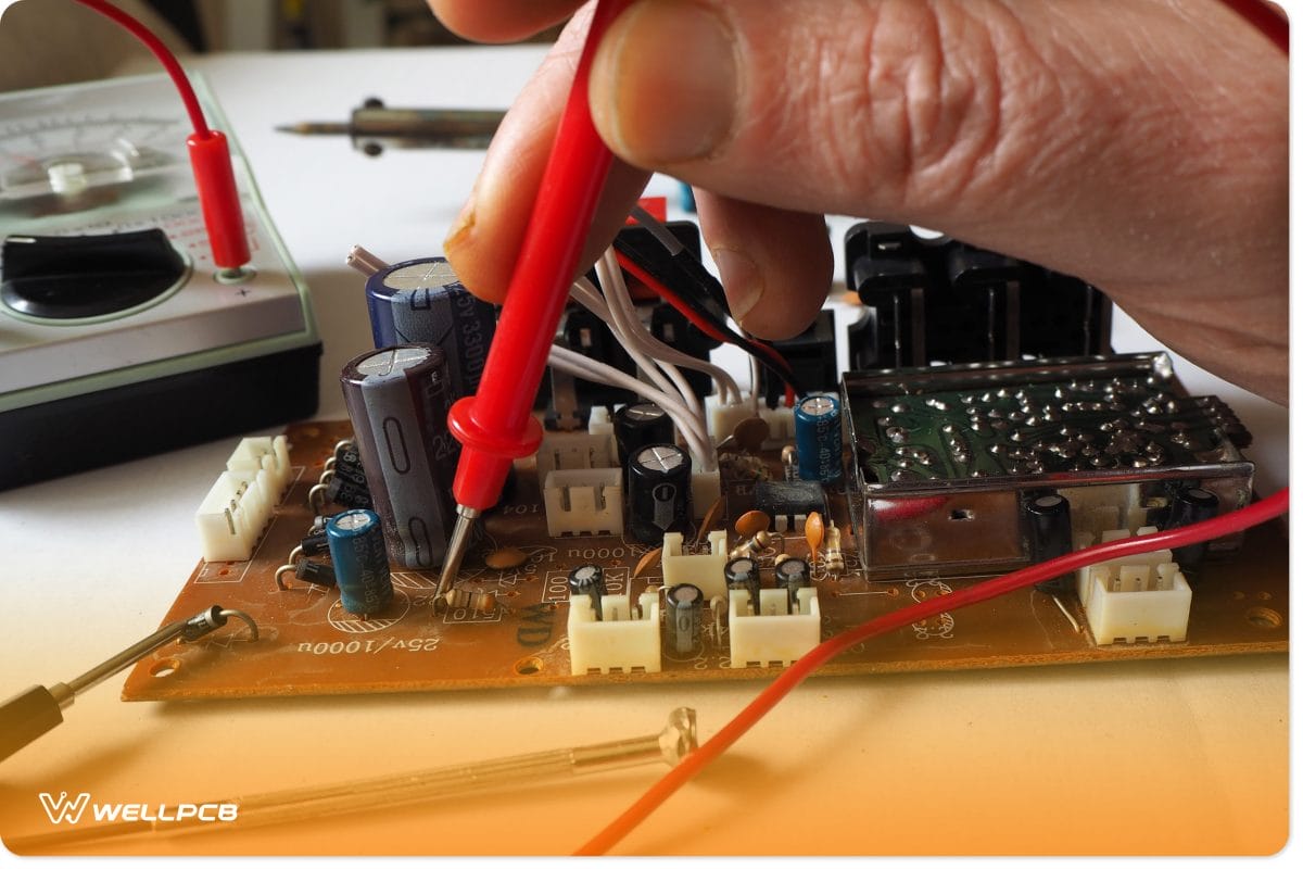
Fig 5: Typical passive oscilloscope probe being used to test an integrated circuit
Source: Wikipedia
A wave’s frequency is the number of times it repeats its shape in a second. We cannot measure a wave’s frequency on an oscilloscope, but we can measure its period. A wave’s period is the time it takes to complete a full cycle. Afterward, you use the formula below to get the frequency. Frequency = 1/period.
Advanced Oscilloscope: AC/DC/Ground Coupling
We use DC coupling when working with DC signals and AC coupling for AC signals. AC coupling eliminates the DC component of your signal so that it oscillates around zero. It allows you to zoom in and measure small AC signals.
If you only want to measure the AC signal without the DC offset, use AC coupling. However, use DC coupling if you only wish to use the DC component or both AC and DC.
Also, you may have an option to couple to the ground. Doing so gives you a flat line representing the zero-volt position. Next, use the vertical position control to line your signal with one of the grid lines. You’ll use this lineup as your ground marker.
Advanced Oscilloscope: Dual Channel Measurements
You can study several inputs simultaneously if your oscilloscope has multiple channels. For example, you can look at a sensor’s timely response and measure the signal out, phase changes, and effects of a filter.
Advanced Oscilloscope: X-Y Mode
The X-Y mode is useful when plotting one signal versus the other. Such instances include plotting the current-voltage curves for diodes and other electrical components.
Conclusion
Oscilloscopes are robust and easy-to-use apparatuses that you should have for your electrical projects. They’re not only efficient but very accurate when set up accordingly. And they don’t require any particular skill or knowledge to operate.
After going through today’s article, you have sufficient knowledge to commence your project. Feel free to contact us for assistance or if you have any gray areas that need clarification.