Contents
HT12D Pin Configuration
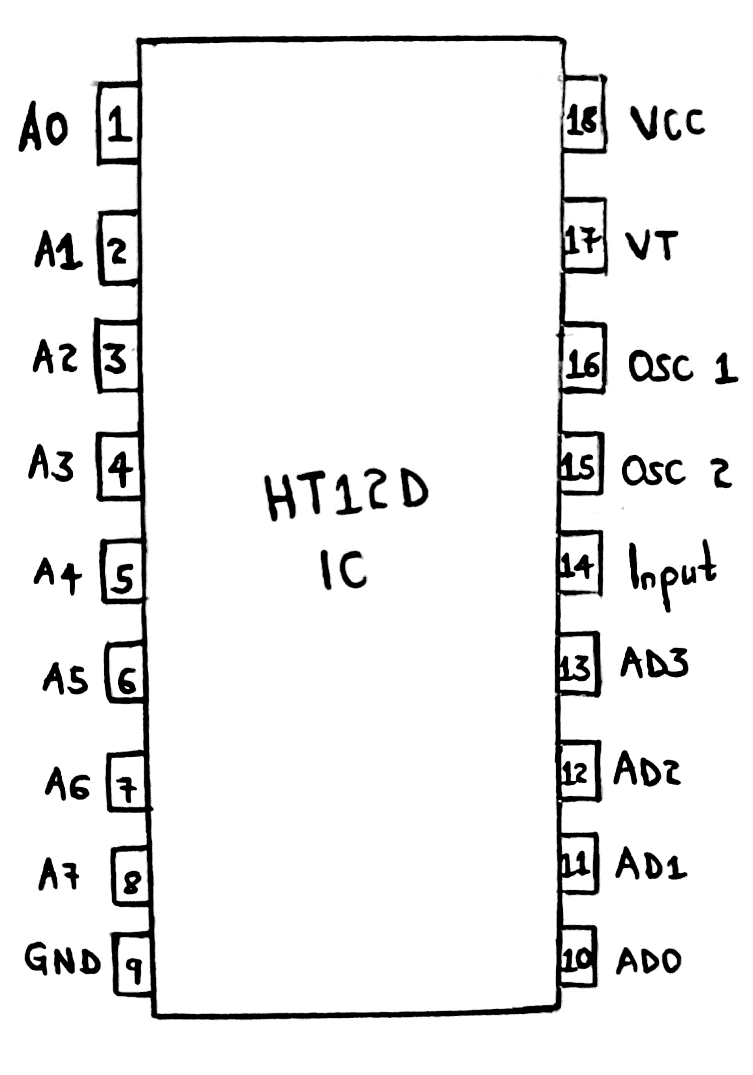
Pinout diagram of HT12D
The usable pins in an HT12D include;
Pin1 to Pin8 (A0, A1, A2, A3, A4, A5, A6, A7, A8) – The first pins are the 8-bit address bits. They protect data. Therefore, before pairing a decoder and encoder IC, always set the bits in a similar pattern.
Pin9 (VSS/Ground pin) – It connects to the circuit’s ground. Moreover, it allows the decoder to operate with external modules and devices.
Pin10 to Pin13 (AD0, AD1, AD2, AD3) – The third set of pins decode data from HT12E IC to acquire data bits. The output data is in logical voltage form.
Pin14 (Input pin) – It receives encoded 12-bit output data gotten from HT12E IC.
Pin15 and Pin16 (OSC1 and OSC2) – They represent the inbuilt oscillators. You can use them by connecting a 1M resistor to the pins.
Pin17 (VT/ Valid Transmission) – Pin17 often goes high after receiving data, even though it’s unnecessary.
Pin18 (VDD/VCC) – Finally, we have the VCC pin that provides a 5V power supply to the IC.
The Features of HT12D
The features and specifications of HT12D are as follows.
- First, it has a standard operating voltage of 5V, but the supply voltage can range from 2.4V to 12V. 5V is better because you’ll have smart boards and multiple controllers.
- Being a design from Low-power CMOS technology, it possesses high noise immunity and low power.
- Thirdly, its operating temperature ranges from -20°C to 75°C even though -50°C to 125°C is also favorable.
- You can pair HT12D IC with HT12E encoder only.
- Further, it has an inbuilt oscillator with a frequency of 150KHz (51K ohm resistor at 5 volts).
- It can directly interface with IR and RF wireless transmissions. Besides, the vital transmissions assist external devices in learning about the status of decoding.
- It also has a current of 0.1uA at 5V (VCC) as a low stand. Additionally, it can have a standby current of 400uA at 12V and 4uA at 5V.
- Then, its decoded data has eight address bits and 4 data bits (4+8 = 12 bits). And it’s often without the use of a third device.
- Finally, it’s available in a 20-pin SOP or 16-pin DIP.
How does the HT12D work?
The basic function of an HT12D IC is decoding 12-bit data getting into the decoder via the input pin. It’s worth mentioning that the in-built oscillator makes the working of the IC easier.
Working steps
- Begin by powering the IC with 5V at pin18 and keep pin9 grounded.
- Next, connect OSC2 (pin16) and OSC1 (pin15) through a 470K resistor to make the IC start decoding data.
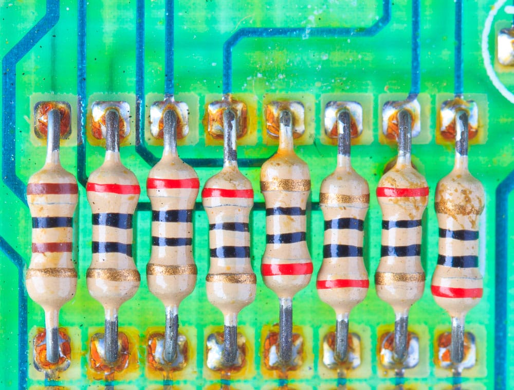
(resistors in circuit board)
- Eventually, you’ll obtain the 4-bit output data at pins AD0 to AD1 (the output pins).
- At the same time, you’ll have to set the address of 8-bit with pins A0 to A7. Remember to keep them in a high or low state.
Note: The decoder and encoder must have a similar address.
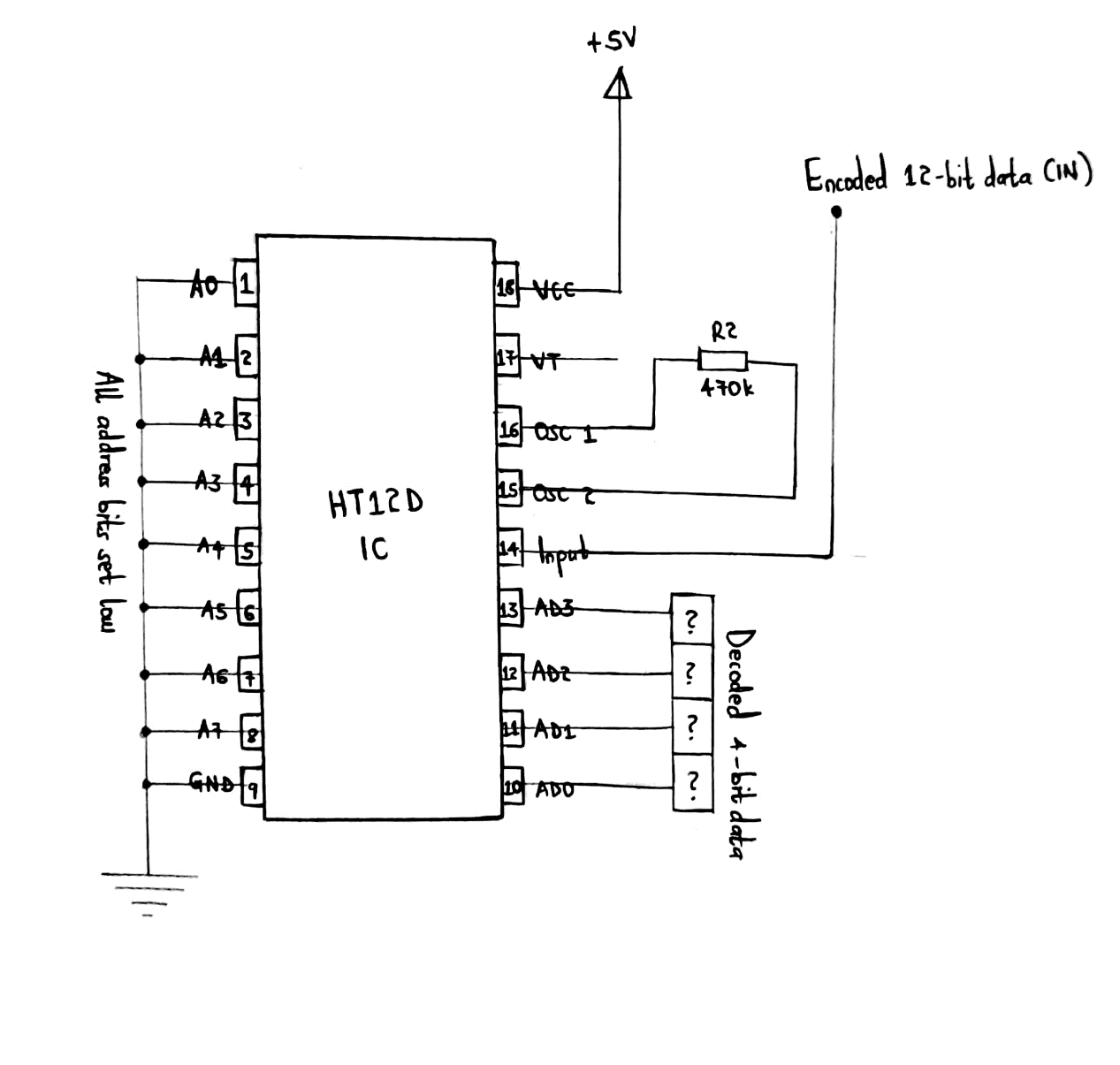
A basic circuit diagram explaining HT12D working
The above circuit is a practical illustration of working HT12D.
The 8-bit address data is 0b00000000 and is achievable by connecting each address pin to the circuit ground. For higher security, connect one of the eight pins to 5 volts.
Furthermore, the circuit receives a +5V power supply from a voltage regulator such as IC 7805.
Output data pins AD0 to AD3 are connected with any Digital IC to help read 4-bit data. You can also attach the pins to the LED to view the data received physically.
The ‘?’ at the decoded data are unknown because the data Encoder IC sends to the input pin is unknown.
HT12D Circuit
Circuit examples using HT12D comprise;
- A circuit with RF Decoder.
- RF receiver and transmitter.
- HT12D RF Receiver. HT12D dominates IR and RF modules to prevent the server from flooding with communication.
- Variable address whereby companies prefer HT12D because of their performance and speed.
HT12D Alternatives
Some of the alternatives for HT12D are 74C922 and PT2272.
- Applications
You will mostly find HT12D IC in the following applications;
- Conversion of parallel 4-bit data to series data,
- Wireless communication projects that involve IR and RF,
- Remote-controlled systems such as cordless telephones, car door controls, car alarm systems, and garage doors,

(a cordless mobile phone)
- Safety systems, for instance, fire/smoke alarm systems and burglar alarm systems,
- Home automation that aids in short-range remote switching.
Conclusion
All in all, HT12D decoders have revolutionized electronic circuits by helping devices decode 12-bit data. In other words, out of the 12-bit, 4-bit transmits data while 8-bit sets decoder address bits. Then, they are common in IR or RF pairs.
As we end the post, we’re urging you to reach out if there’s anything amiss or for further knowledge. We’ll be glad to help.