Generally, an IC 4060/CD4060 timer chip is a Timer IC or oscillator in some instances. It belongs to an IC 4000 series of Integrated Circuits and operates in a power supply ranging from 3V to 15V. Other than using it to get a high-graded time precision during oscillation of desirable frequencies, you can also use it to produce variable time delays or intervals that are discretely accurate. What’s more, with an IC 4060, you will only need a few external components as requirements for an oscillation’s initial operation.
In this article, we will tackle the basics of a CD4060 timer.
Contents
IC 4060 Working Principle
An IC 4060 comes with an in-built oscillator module and a binary counter. The module produces a signal that has a definite frequency. As such, as the oscillator runs while working, the counter records the number of oscillations. In the end, there will be a reflection in the output pinouts of IC 4060.
Also, due to being a binary counter, there will always be an increase of the counter value by one in binary numbers for each negative transition of the clock pulse. Furthermore, you need to have the reset input on the ground line or connect it with a negative power supply. Should you apply a +v signal here (say one or higher), you will reset the oscillations/ counter and have it restarted from zero.
IC 4060 Pin Function
In summary, while referring to the timer circuit diagram, these are the functions of the IC 4060;
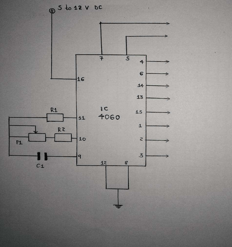
Pins 1, 2, 3, 4, 5, 6, 7, 13, 14, and 15 are the output pins, and they generally work as follows;
- First, they can give the cock signal output.
- They can also produce the ON/OFF time delays.
- Again, through the pinouts, you can get the frequency at different levels. Often, it depends on the resistor’s Rt (pin10) and capacitor’s Ct (pin9) values.
In the pinout order 7, 5, 4, 6, 14, 13, 15, 1, 2, and 3, you will find that pin3 generates the least frequency while pin7 generates the highest frequency. Moreover, as the frequency continues in a similar order, it becomes half the proportion.
For example, if a capacitor/ resistor value at pin 10/9 causes pin7 to produce a 1 kHz frequency, pin5 will generate 500 Khz, pin4 – 250 Khz, pin6 – 125 Khz, and so forth.
Then, pin 9 (CEXT), 10 (REXT), and 11 are input pins.
They can initiate the IC 4060’s frequency/ oscillation provided they have connections to required passive components.
Pin 12 (RST) is majorly the reset pin.
Its function is to reset the counter value to 0, besides disabling the oscillator.
Pin 16 is the VCC/VDD (+) voltage supply pinout, whereas pin 8 is the VSS (-) supply pinout.
IC 4060 Binary Counter Features
A couple of the IC 4060’s binary counter features include;
- A max. clock frequency of 30MHz at 15V,
- A medium-speed operation of 8 MHz (typ. at VDD = 10V),
- A reset propagation delay at 25 ns at 5V,
- A counting range from 0 to 18383 (often in decimals),
- Schmitt trigger inputs that leave room for unlimited rising and falling times,
- Function and pins that are in alignment with the TTL series,
- A fully static operation that has buffered outputs and inputs, and finally
- An RC oscillator frequency of 690 Khz minimum at 15V.

IC 4060 Timing Cycle Calculations
First, we should figure out how an IC 4060 works and its usage procedure before incorporating the clock cycle calculations.
- Begin by connecting pin 16 to the +ve supply terminal and pin 8 to the -ve supply terminal. Even though some IC 4060 support up to 20V, the most recommendable power supply voltage ranges from 3V and 15V. Luckily, the datasheet should clarify the exact values.
- Then, have the following stepwise connection to activate the oscillator; connect a resistor from pin 10, a capacitor from pin 9, and another resistor pin 11. Next, have all three connections joining at the other end as per the diagram.
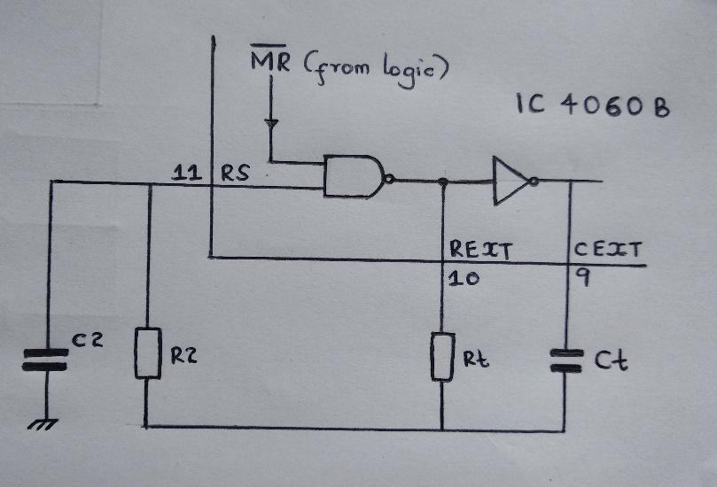
From the diagram, we can see that Ct and Rt have a configuration around a NOT gate and a NAND gate. Rt and Ct determine the frequencies and delay internals crossway the IC 4060 outputs.
Formula for calculation Ct and Rt values;
f (osc) = 1/2.3 x Rt x Ct
(2.3 is a constant value in the ICs internal configuration)
The values below also essentially contribute to a normal working of an oscillator;
Rt << R2 and R2 x C2 << Rt x Ct
From the values;
- R2 reduces the effect of the forward voltage’s frequency on the input protection diodes.
- Further, C2 acts in place of the stray capacitance. To have a better precision of the output time intervals, ensure the stray capacitance is at a minimum level. Therefore, Ct should be larger than C2.
- Rt is also recommendable at a large value since it helps in negating the internal LOCMOS resistance. Typical values can be 200 Ω at VDD = 15V, 300 Ω at VDD = 10V, and 500 Ω at VDD = 5V.
- Most importantly, for the best oscillatory action outcome, have the configuration timing parts value in the following conditions;
10kΩ ≤ Rt≤ 1MΩ and Ct ≥ 100Pf, up to any workable value.
Importance of Crystal Oscillator in an IC 4060
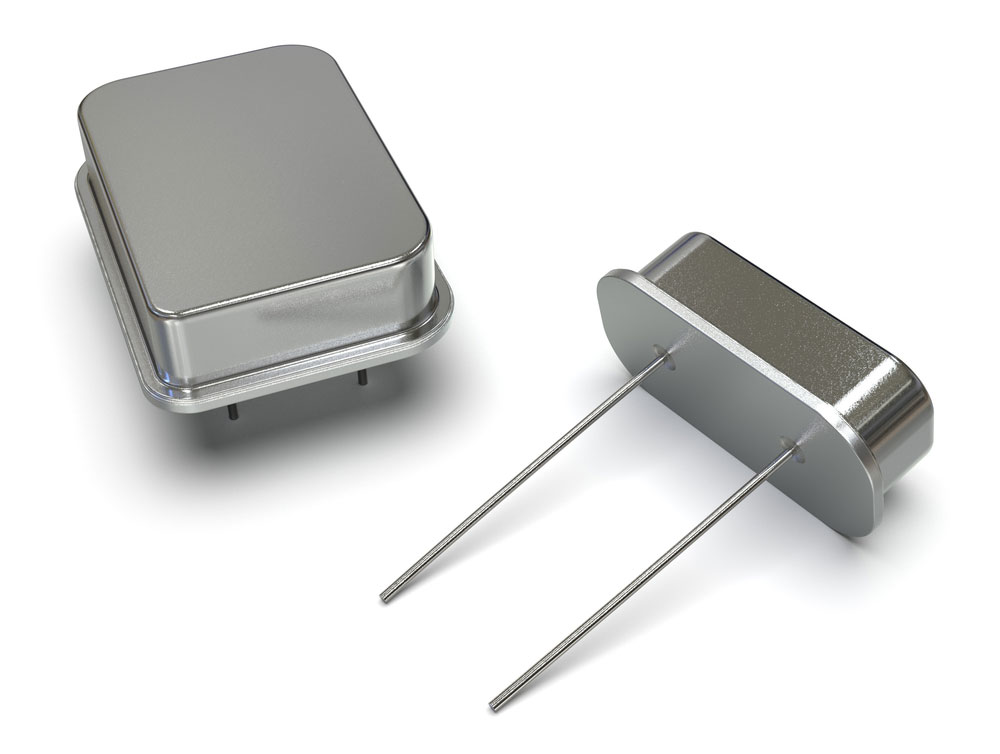
(crystal oscillators).
A crystal oscillator is a device that further enhances the IC 4060 externally even though the timer IC is accurate in its delay periods and oscillations. Often, the crystal oscillator will prevent the frequency from drifting into an unintended value. It does this by locking up the frequency to the predetermined value.
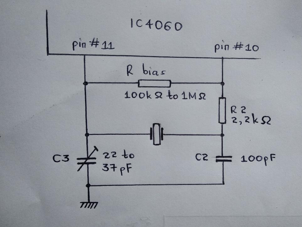
Explanation on the diagram.
- First, we’ll only use pin10 and pin11 to integrate the IC 4060 with the crystal oscillator.
- Then, R2 is the supply voltage and ensures the smooth running of the crystal oscillations.
- Additionally, capacitors C2 and C3 ensure the crystal gets to its expected resonance frequency. However, if need be, you can slightly change the crystal’s resonance value by tweaking C3. Subsequently, the IC 4060 output frequency will also shift.
Note; Alternatively, you can use a ceramic resonator instead of a crystal device. But in both cases, you might have low accuracy when oscillating for a longer time period.
FAQs
How can you automatically achieve an Automatic power switch ON reset?
First, it is crucial to enable the automatic power switch ON reset on IC 4060. The automation helps in initiating the Integrated Circuit clock and counting the timing process from zero. However, when you fail to include the automatic power reset, you will have an IC with a random initialization when the counter process begins. Again, the initial timing process won’t be at zero, but rather, at an intermediate level.
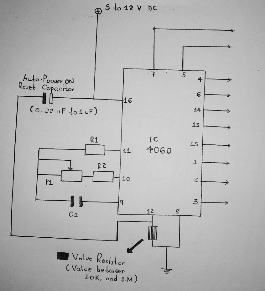
Thus, to achieve an automatic power switch ON reset for IC 4060, we have to add an RC network with a functional IC reset pinout as follows;
- Usually, you will directly connect pin 12 to the ground line. But this time, you need to use a high-value resistor e.g., a 100K, as an intermediate before getting to the ground line.
- Afterward, join up a small value capacitor (say 0.33 uF to 1 uF) from the +ve end to pin 12.
Finally, your IC 4060 timer circuit now has an enabled auto-reset feature.
How do you connect the Reset Pin?
In normal circumstances, pin 12 is the timer’s reset pin. Moreover, its connection is always on the ground line or to the -ve supply.
Therefore, introducing a +ve supply pulse to the IC 4060’s input will revert the IC/ reset the oscillations. Consequently, the oscillations or counting process will begin from zero, and the outputs will also lead towards a zero logic.
How to achieve adjustable timing
You can start by replacing the variable resistor Rt with a potentiometer device at pin10 of the IC 4060 timer circuit. The potentiometer alternative helps by producing an adjustable frequency output crossway to the IC 4060’s output pins.
As a second option, you can also alter the capacitor Ct value to change the IC timer’s frequency.
Conclusion
To summarize, an IC 4060 is easy to work with because it does not depend on external clock input. Besides that, the in-built oscillations put it at a higher advantage since you’ll only require a few electronic components to use it. Also, it has numerous applications in electronic technology, such as in counter circuits, timers, frequency dividers, etc.
(a timer circuit).
We are open to questions, comments, or inquiries. And so, do not hesitate to contact us.