Adjustable voltage regulators are essential in load regulation. They are handy in delivering variable DC power supply, which is vital in electronics because of their versatility. An example of such a controller is the lm317 voltage regulator, which forms the basis of our discussion. It is the ultimate lm317 voltage regulator datasheet. Thus, for more insights on the current regulator, keep reading.
Contents
What is an lm317 Voltage Regulator?
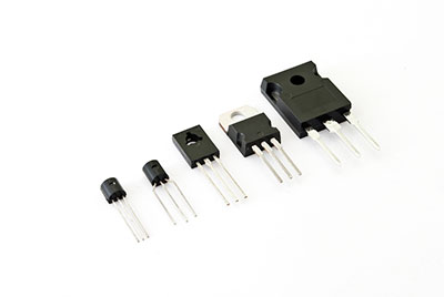
3-pin Terminal Transistors
The Lm317 is an adjustable 3-terminal positive voltage regulator. Also, It’s capable of supplying a load current of more than 1.5A. But, to round it up, it has an adjustable output voltage in the range of 1.2 Volts to 37 Volts.
lm317 Voltage Regulator Pin Configuration
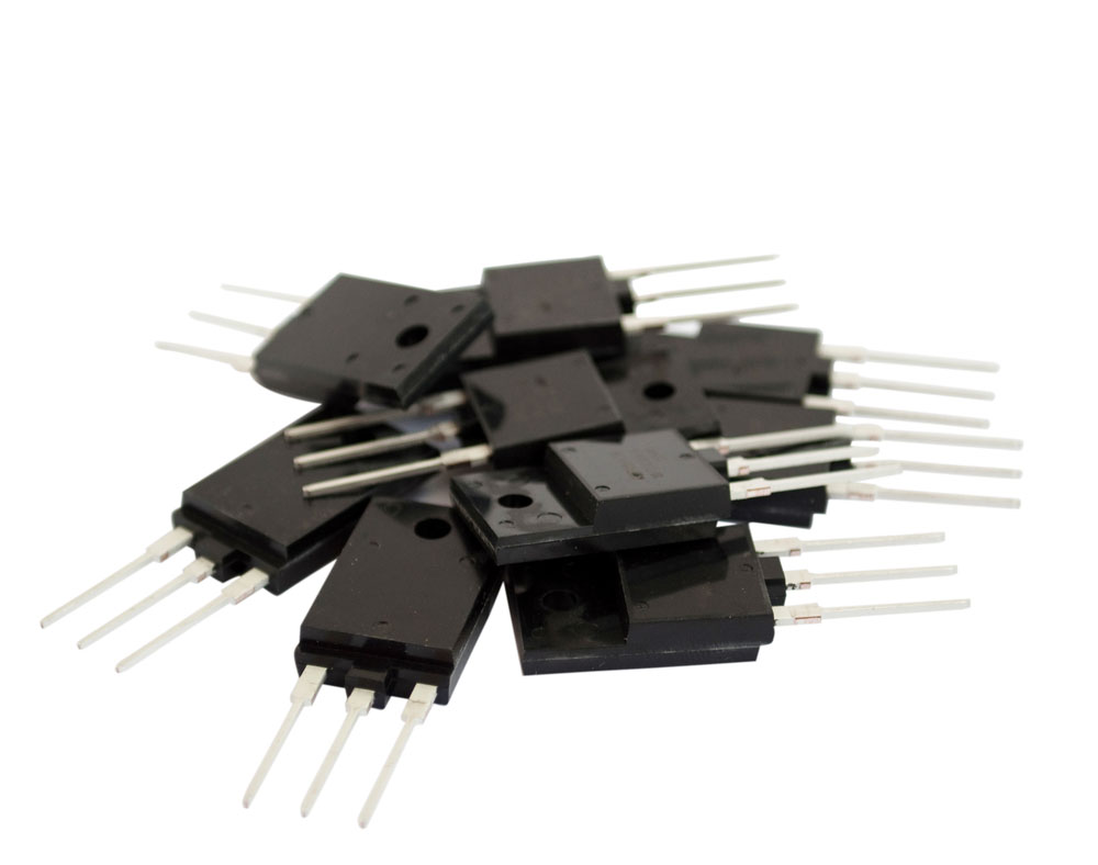
Numerous Lm317 voltage regulators
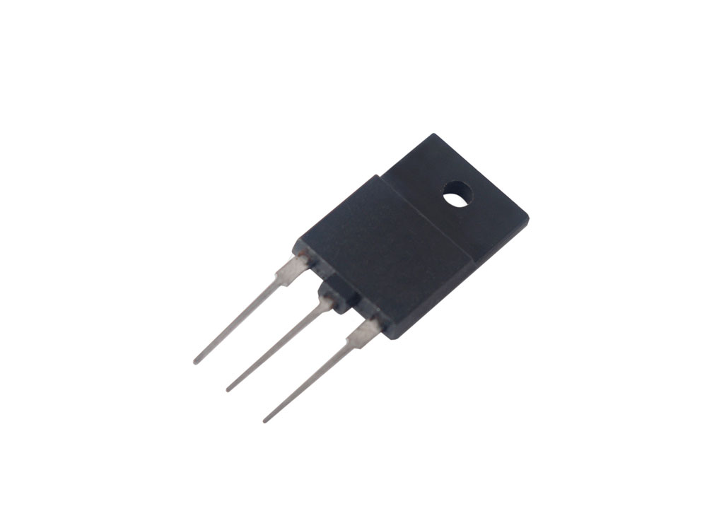
The device has three pins, each with a particular specific function.
Pin 1 is the Adjustable Pin. Thus, its role is to adjust the output voltage.
Pin 2 is the Output Voltage Pin (Vout). Once the voltage has been adjusted by pin 1, it leaves the IC via this terminal.
Lastly, Pin 3 is the Input Voltage Pin (Vin). Also, it’s a vital terminal via which current enters the IC.
lm317 Voltage Regulator Features
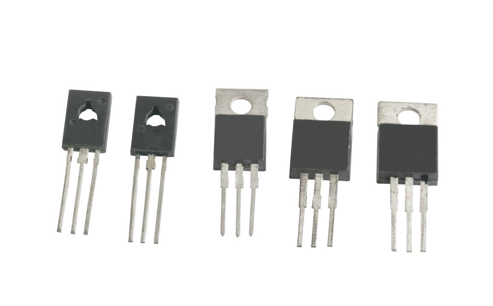
A 3 pin transistor
The following are critical features of this variable voltage regulator.
- First, it can deliver an output current of at least 1.5A. Also, its voltage can extend from 1.2V to 37V output range.
- Secondly, it has internal short circuit protection. Thus, its output cannot be short-circuited internally.
- Thirdly, it features an internal thermal overload cushion. Hence, its current limit remains constant even with a temperature rise.
- Further, it retails in TO-220, SOT223, and TO263 packages, similar to 2SC1061 transistors. Also, it is synonymous with a 1% output voltage durability.
- Fifthly, it has a ripple rejection of 80 dB and an operating junction temperature of 125°C.
- Lastly, it features a maximum output current of 2.2A when its voltage difference is 15V.

How to use lm317 Voltage Regulator
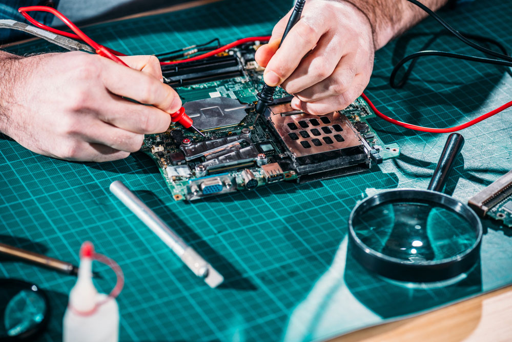
An engineer testing a circuit
The voltage regulator is simple to use, and it is also versatile with its applications.
Primarily, the input voltage enters via Pin 3. Next, the voltage enters the adjustment terminal via a potential divider. Ideally, the wall will be a pair of resistors.
Next, the adjustable terminal will determine the voltage that leaves via the output pin. Note that it cannot be yet a variable regulator without the potential divider. Thus, the use of a potentiometer in the divider pin is inevitable.
Check out the circuit diagram.
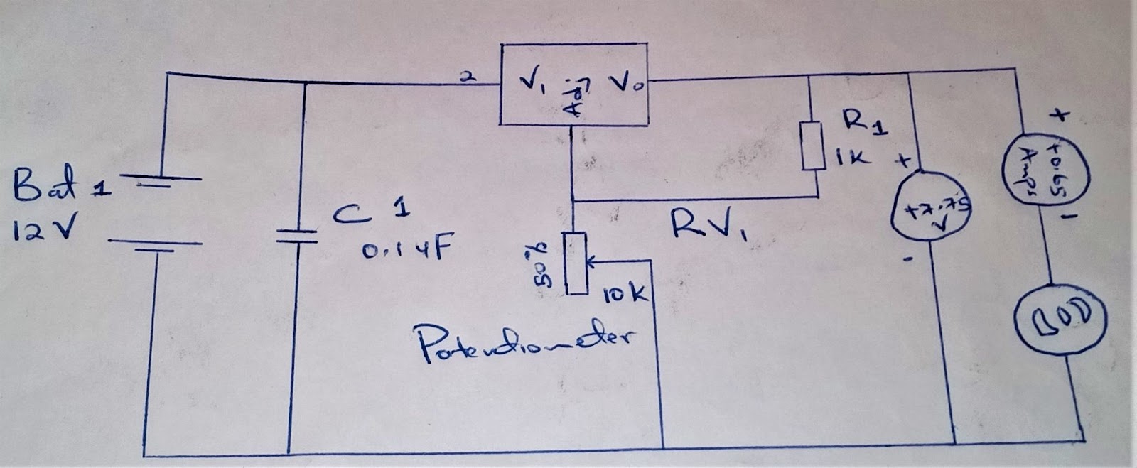
Voltage Regulator Circuit Diagram
The potentiometer plus the resistor (R1) above create the potential difference at the adjustable pin. Furthermore, we can calculate the output voltage range by considering the value of the resistors.
Use the formula: V(out)= 1.25 x (1+ (R2/R1).
lm317 voltage Regulator Application

Voltage regulators are helpful in DVD players.
- Useful in current limiting and reverse polarity circuits.
- Also, it is common in electronic devices such as DVD and desktop PCs.
- Thirdly, it is essential in motor control circuits and positive voltage regulations.
- Lastly, it is valuable for variation of DC power supply.
Conclusion
The LM317 is a component that is handy in variable voltage regulation. Further, you can use it in simple electronics projects to replace 1.5 V or 9 V batteries. Among the key features that make it popular are its high efficiency, ease of use, and low cost.
For additional insights on the voltage regulator or questions, kindly reach out to us.


